D1 to EGA Control Board Upgrade Guide

Step 1

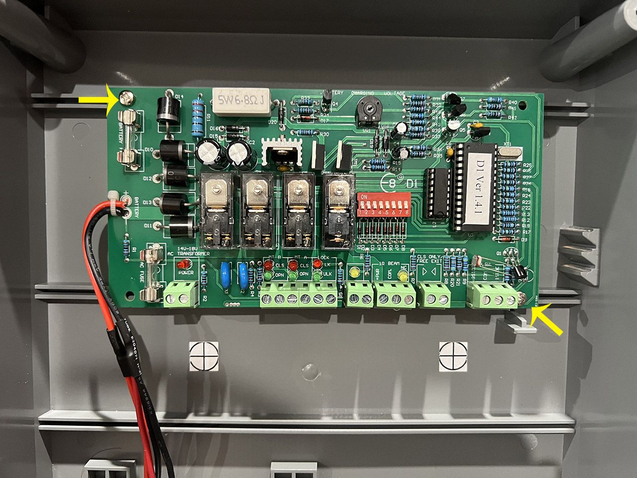
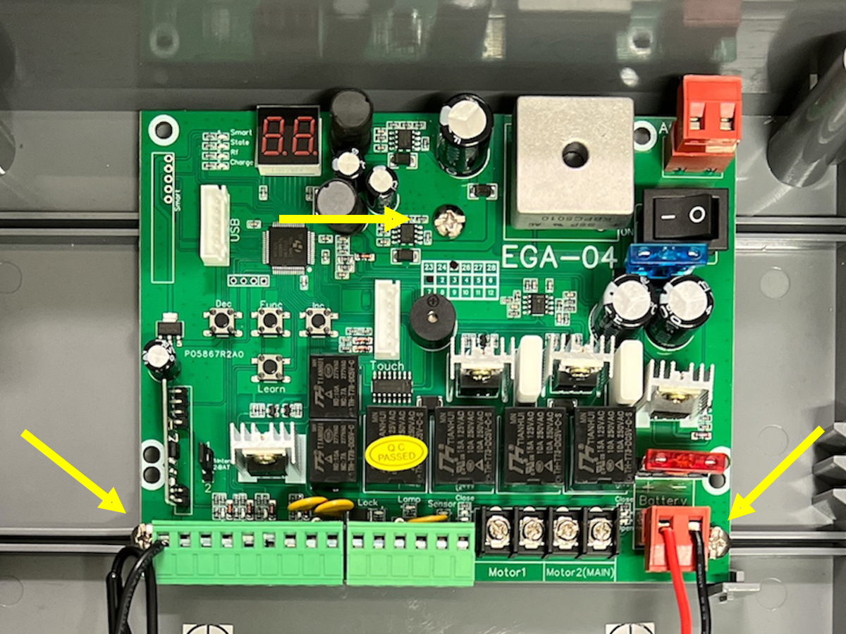
Remove the D1 control board from the main control box by removing the two screws as shown.

Step 2

You are provided with screw 3 holes to secure the EGA control board to the main control box (indicated by the yellow arrows). If you only have 2 screws from your D1 control board, use 1 screw to secure the top section of the control board and the other screw in either of the bottom 2 screw holes.

Step 3

Wire up your actuator arm or arms following the correct sequence as shown below
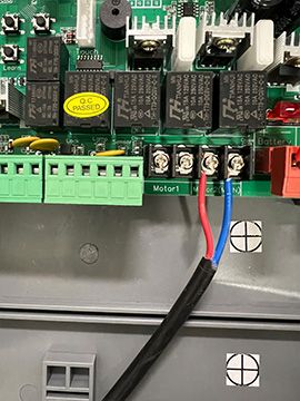
Single arm setup - arm on the inside of the property, pushing the gate outwards to open.
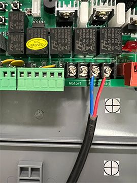
Single arm setup - arm on the inside of the property, pulling the gate in to the property to open.
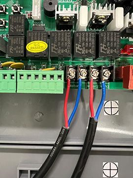
Double arm setup - arms on the inside of the property, pushing the gates outwards to open.
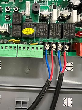
Double arm setup - arms on the inside of the property, pulling the gates in to the property to open.

Step 4 - Accessory Wiring

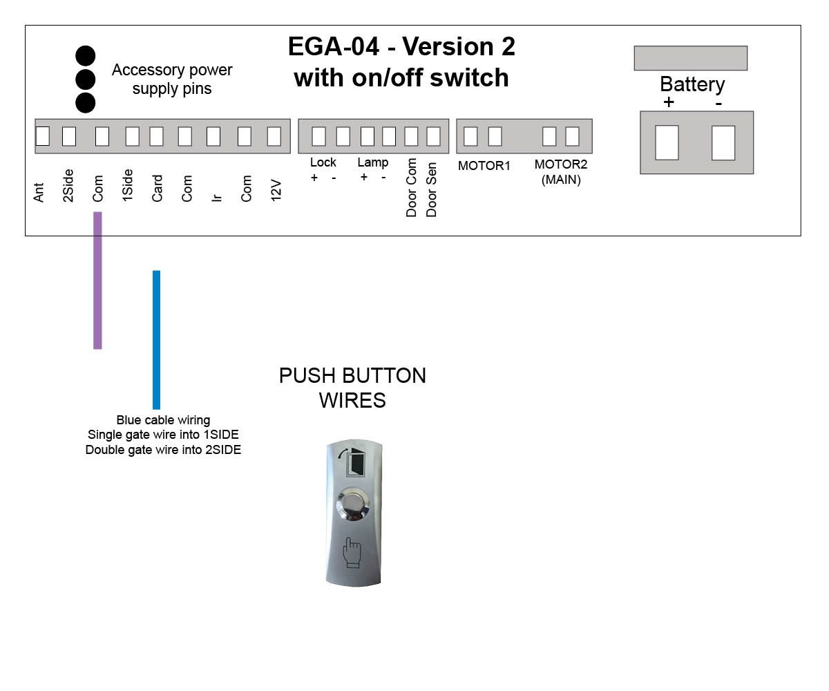
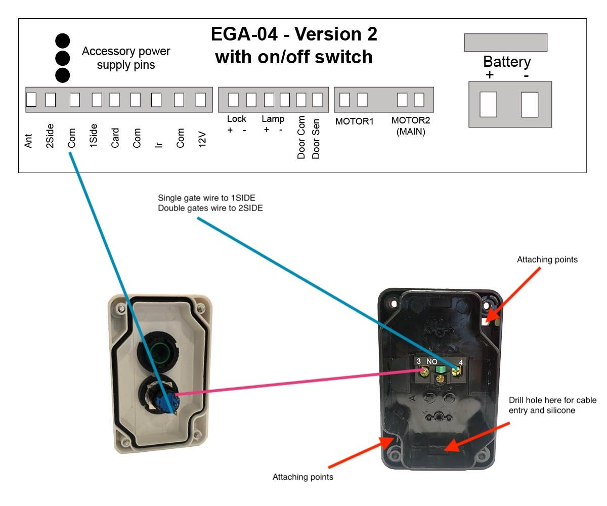
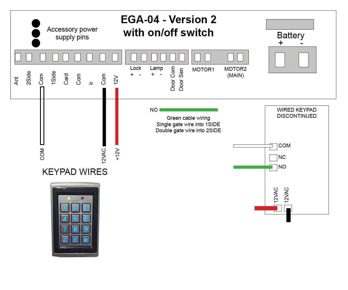
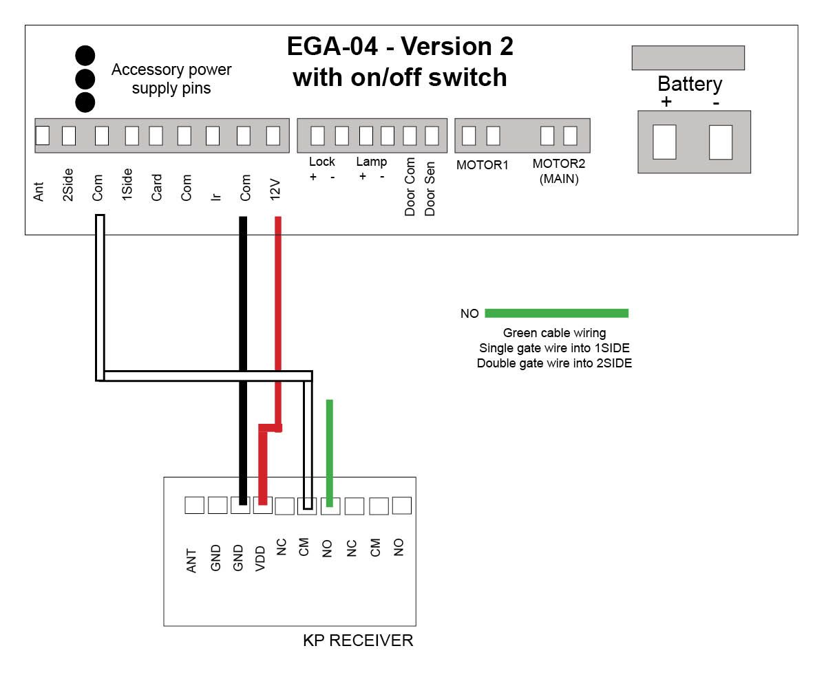
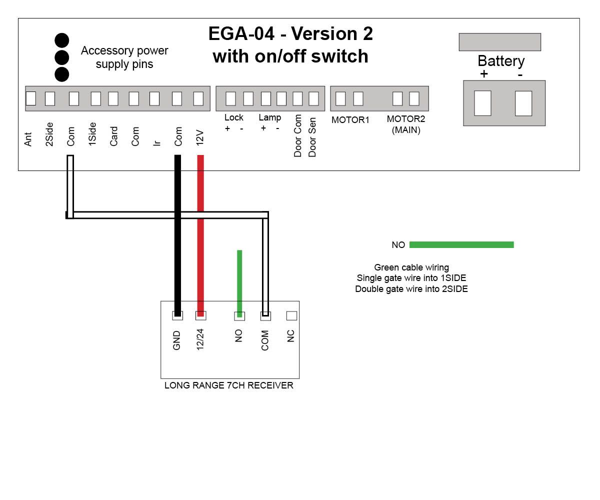
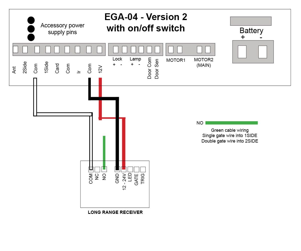
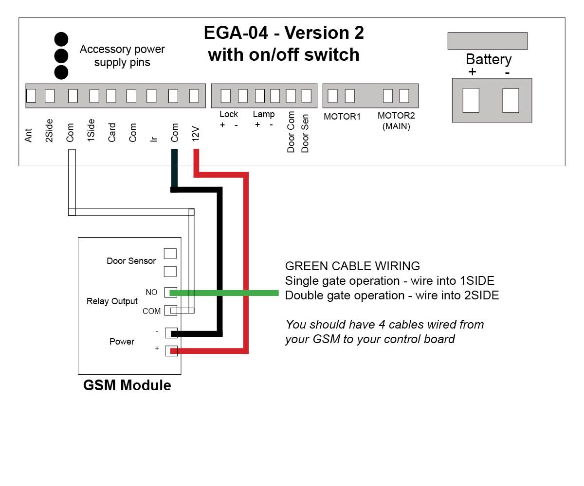
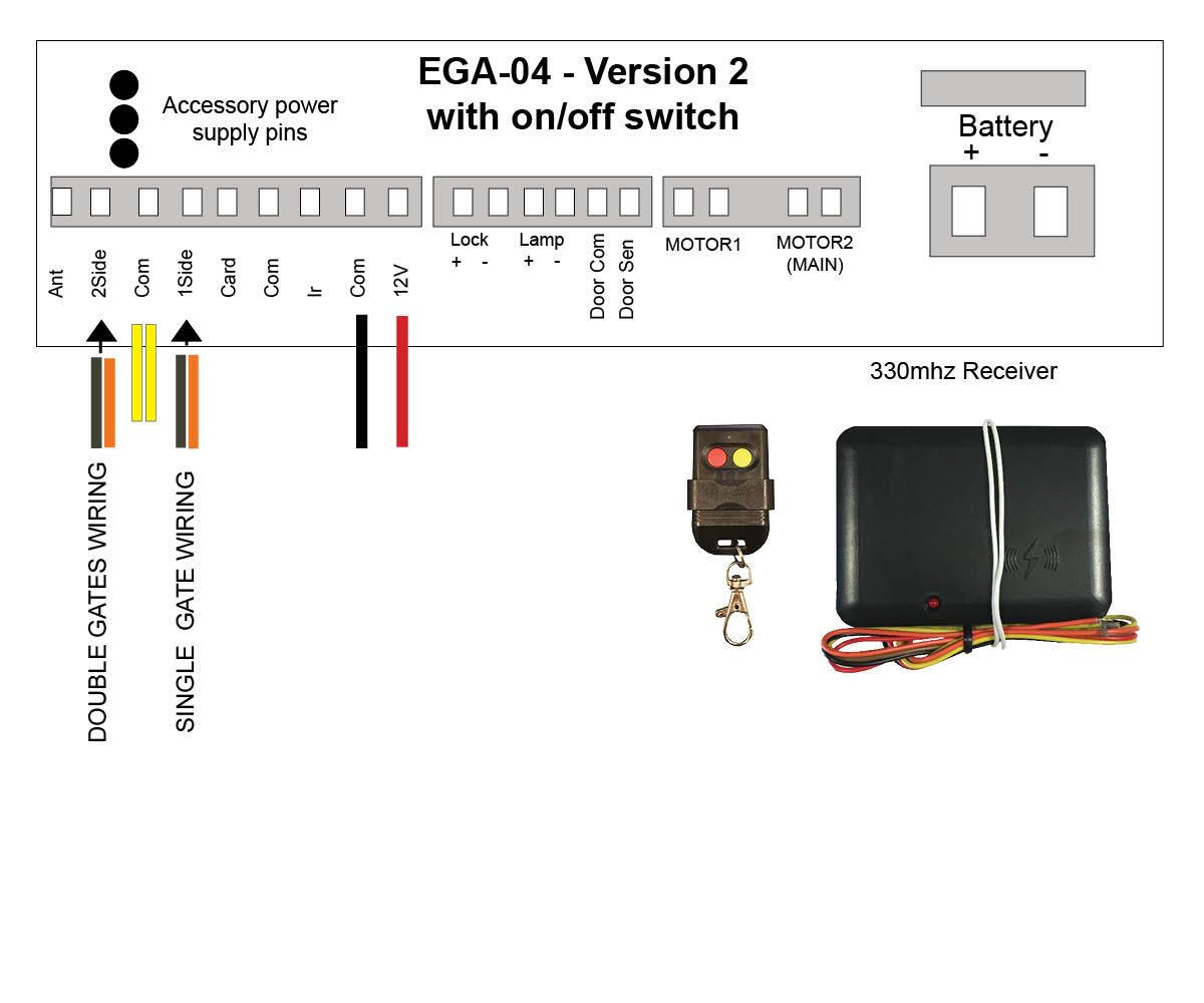
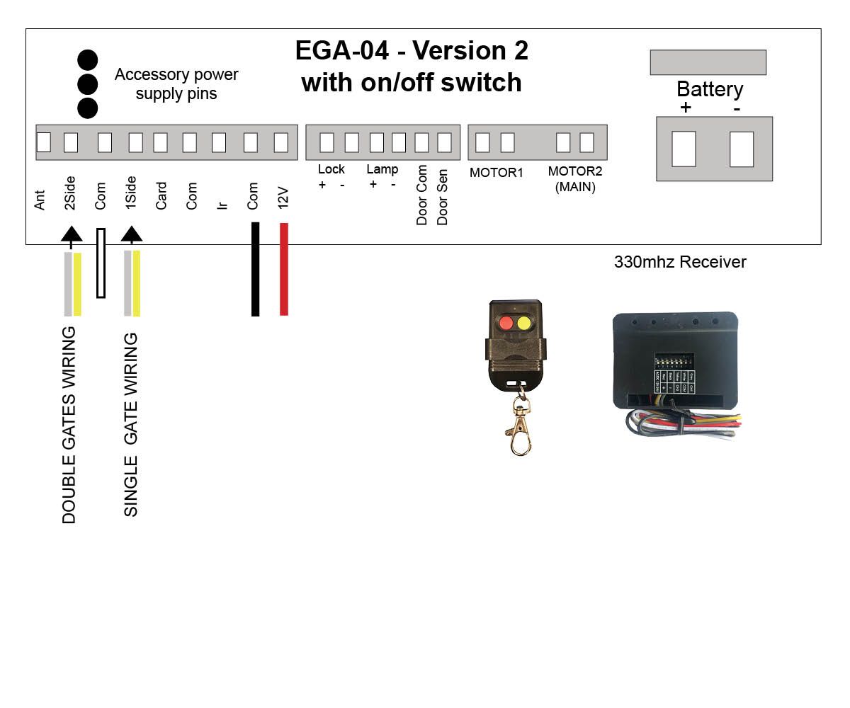
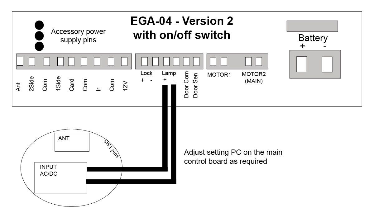
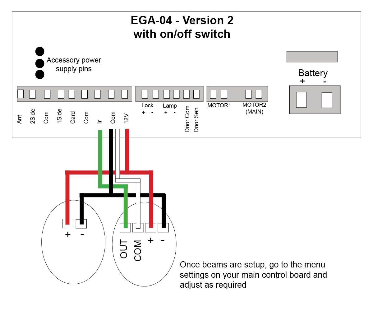
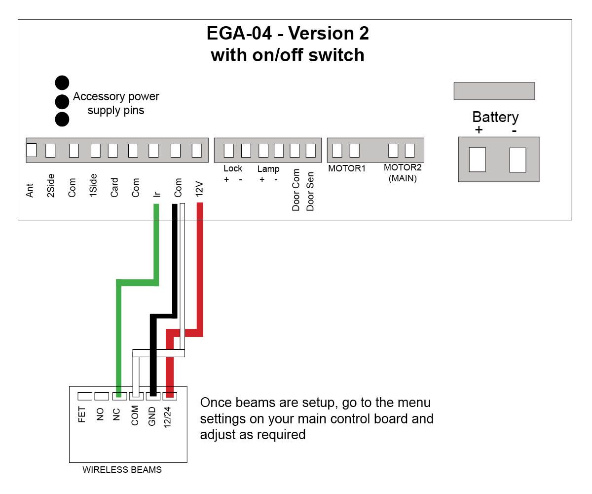
Select your accessory below to view the specific wiring instructions for each item.
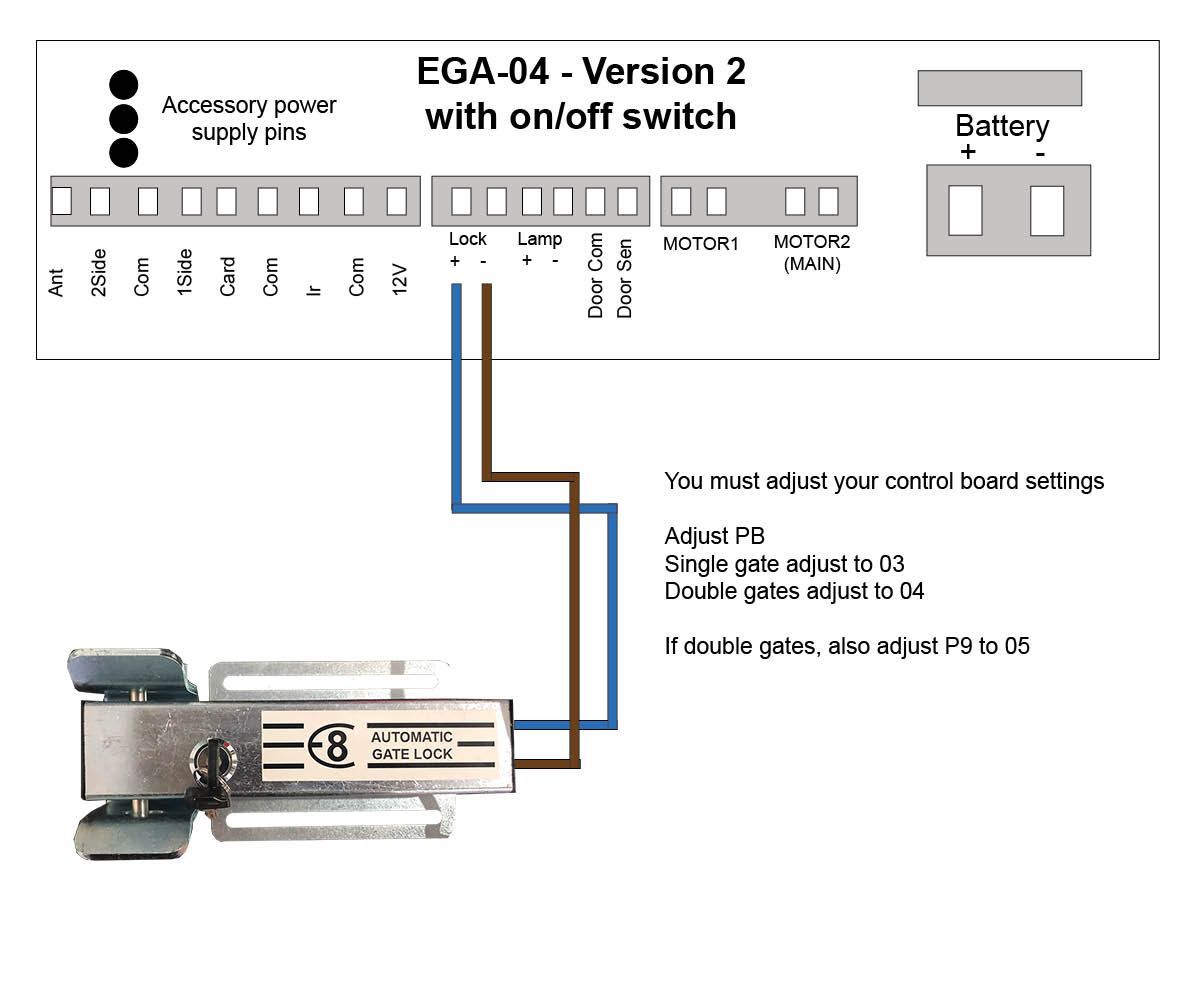
Electric Gate Lock

Setting up your Electric Gate Lock

Menu Settings

To enter the Menu settings, the gate/s must be in either the full Open or full Close position, the control board will not allow you to enter the Menu settings while the gate opener is operating.

Press and hold “FUN” button for 2 seconds or until the Digital Display shows P0. From here use “DEC” or “INC” buttons to go down or up the menu list, once you are on the menu setting you need, press “FUN” button once to enter the setting. Now use “DEC” or “INC” to decrease or increase the parameter number, once you have selected the parameter number you require, press the “FUN” button to confirm the new setting.

To exit the menu setting, press the “Learn” button once.
Now test your adjusted settings.

Step 5 - Power Wiring (Solar or Electric)

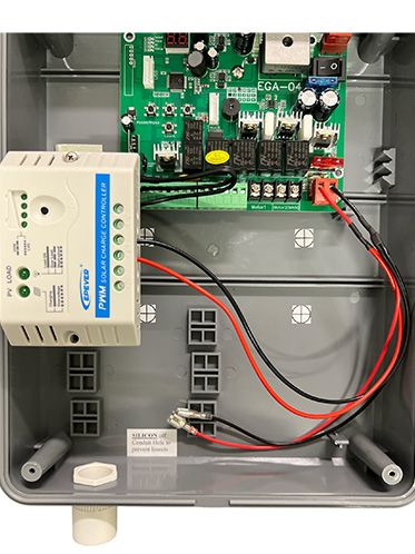
Solar Power

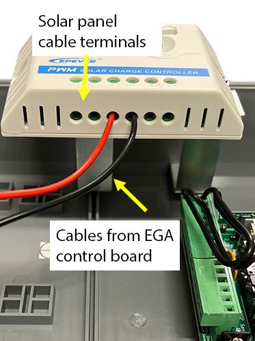
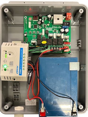
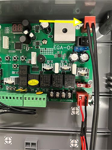
Images below showing the solar panel wired to the solar regulator with the battery connected.
Electric Power

Images below showing the transformer wired to the EGA control board with the backup battery

Setting your Auto Travel Function with the EGA Control Board

After installing the actuator arm/s and completing the wiring as shown above for your gate opener, have the gate/s in the open position.

If your unit is an ELECTRIC kit with a TRANSFORMER, turn your transformer on now. The control board will make a “BEEP” sound and then run through a start-up sequence which you will see on the digital display labelled MENU. Wait 10 seconds for the control board to finalise this step.

If your unit is a SOLAR POWERED kit, connect the SOLAR PANEL to your regulator and connect the battery up to the power cables. The control board will make a “BEEP” sound and then run through a start-up sequence which you will see on the digital display labelled MENU. Wait 10 seconds for the control board to finalise this step.

D1 to EGA Conversion Videos

Single swing conversion

Double swing conversion