Step 2
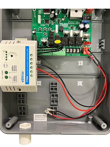
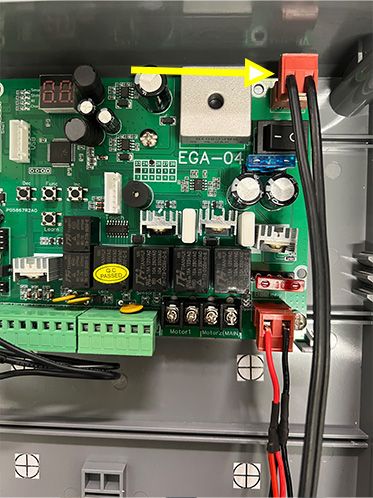
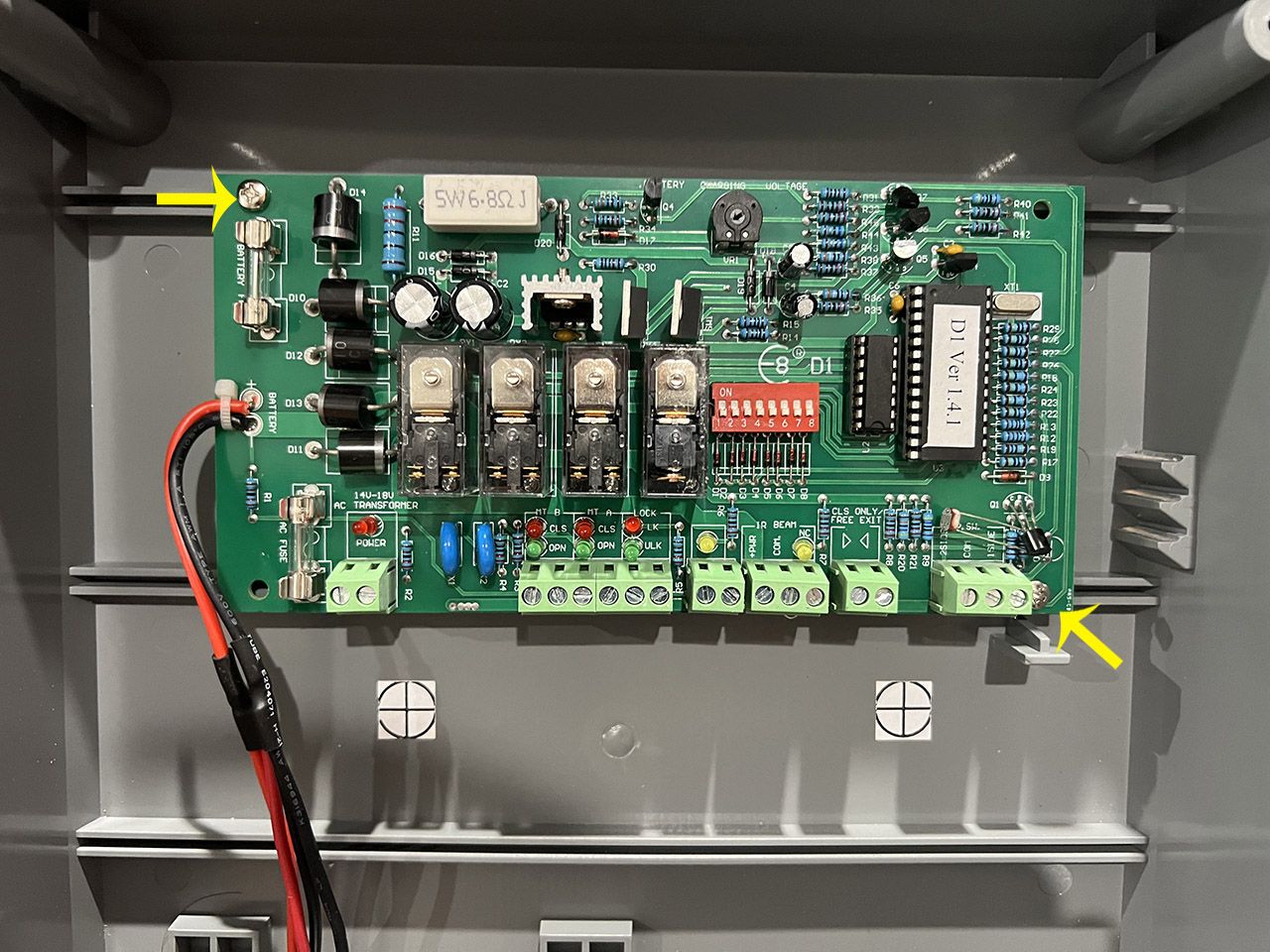
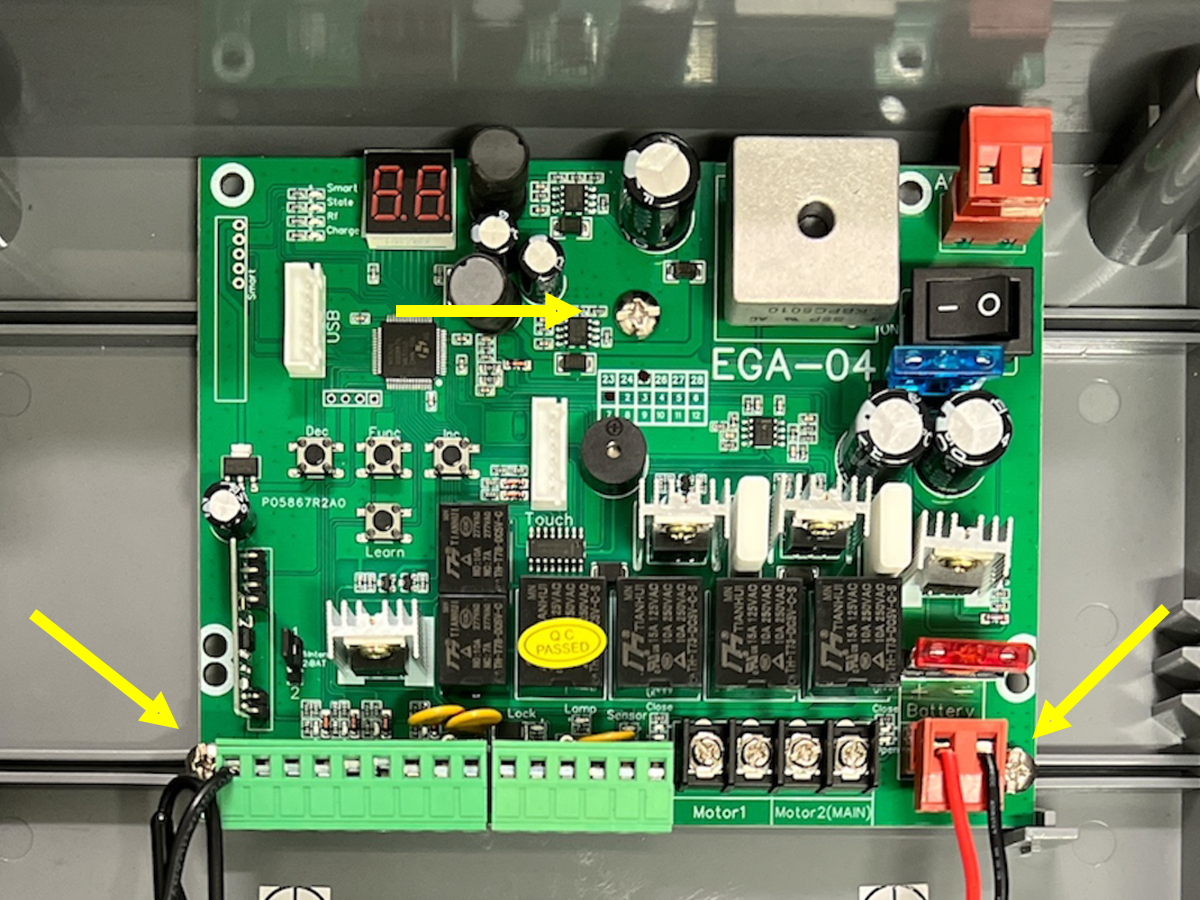
You are provided with screw 3 holes to secure the EGA control board to the main control box (indicated by the yellow arrows). If you only have 2 screws from your D1 control board, use 1 screw to secure the top section of the control board and the other screw in either of the bottom 2 screw holes.

Single arm setup - arm on the inside of the property, pushing the gate outwards to open.

Single arm setup - arm on the inside of the property, pulling the gate in to the property to open.

Double arm setup - arms on the inside of the property, pushing the gates outwards to open.

Double arm setup - arms on the inside of the property, pulling the gates in to the property to open.