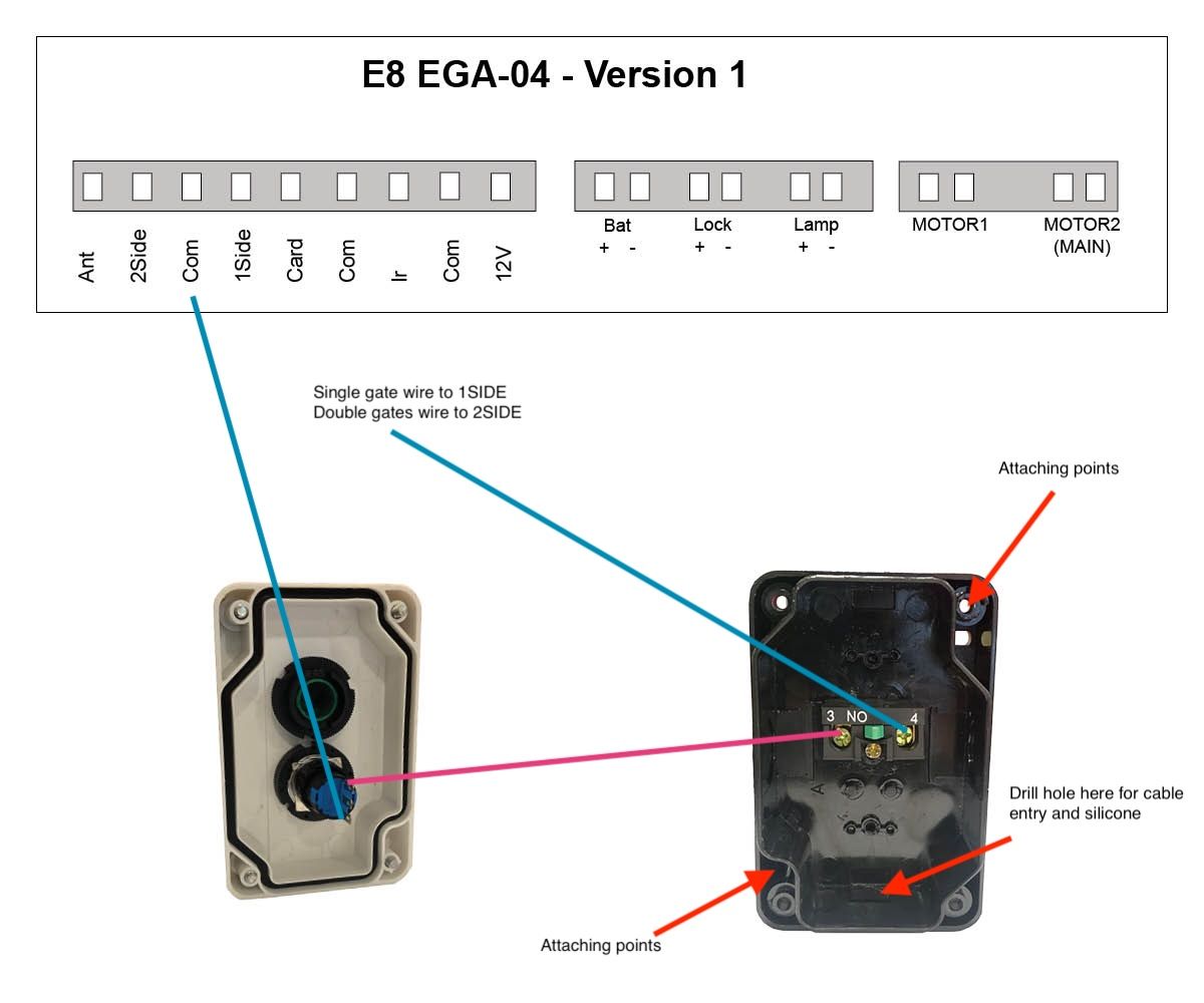
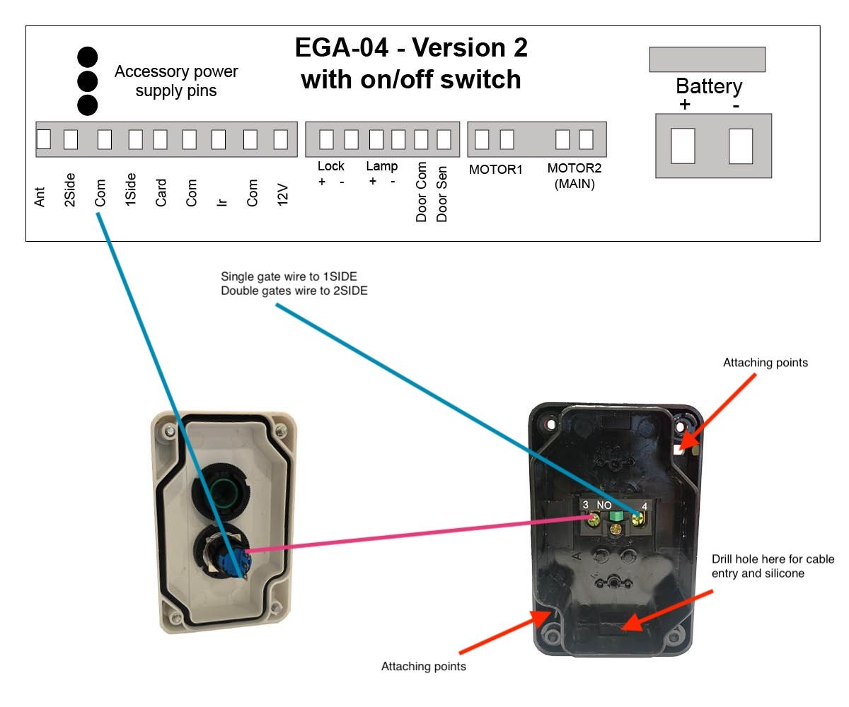
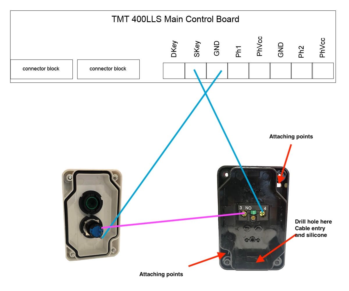
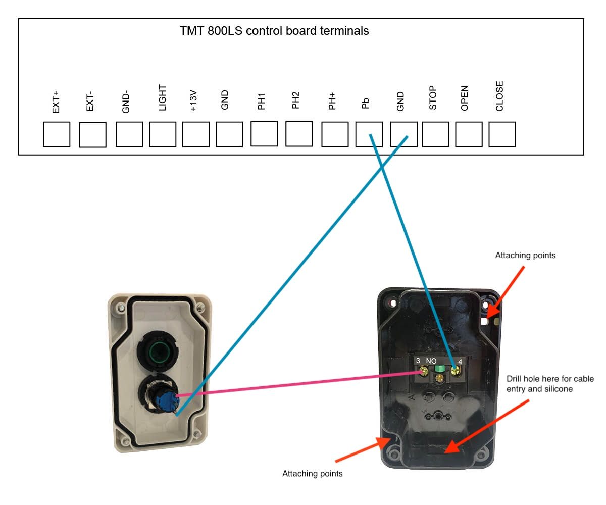
Please note that the coloured cables in our below images are for examples only and may not match the coloured cables that you will be using. When wiring up the push button, you will be able to use the key to lock and disable the button. Follow both coloured wiring instructions (pink and blue) as shown below.
When securing the blue and pink cable to the internal pins of the lock you can either secure by soldering the cable, threading cable through the hole to secure it or secure cable with a connector.
When you attach the push button unit to your post, even though the button housing is a sealed unit, we highly recommend sealing (silcone) all the way around the back housing to prevent any water or insects entering in through your screws. Also when you drill the hole for your cabling at the bottom of the unit we recommend to silcone up that entry point.
We recommend every 6-12 months to do a thorough check over the push button and it’s internals to make sure there is no insect infestation and that everything is still in good working order.
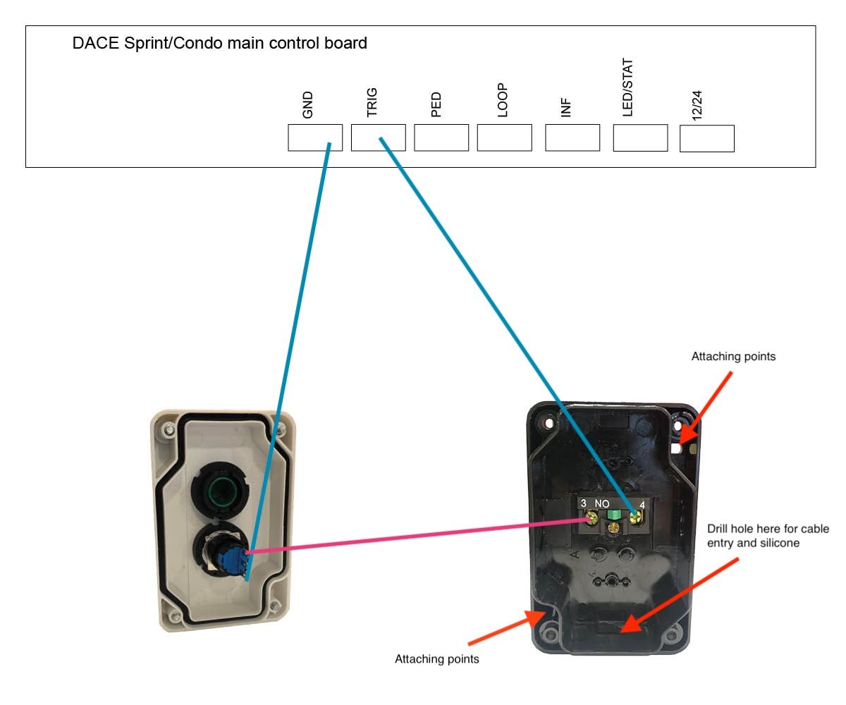
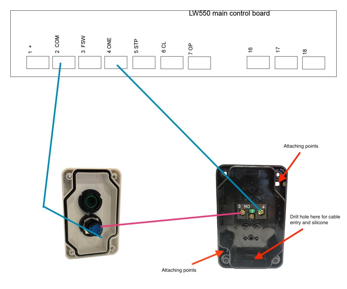
Blue cables
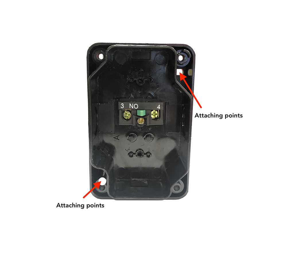
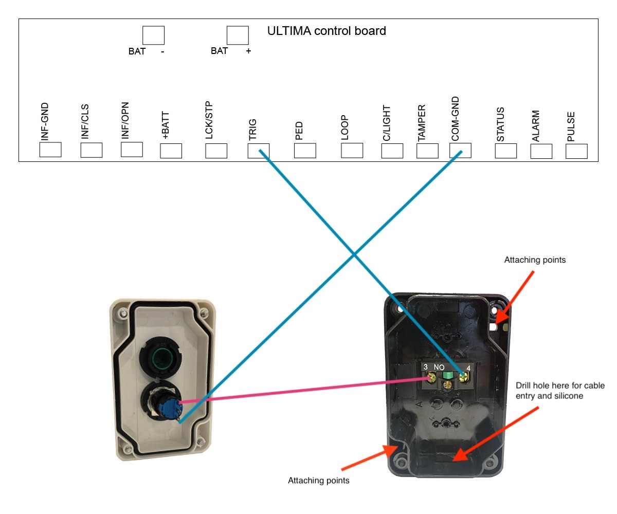
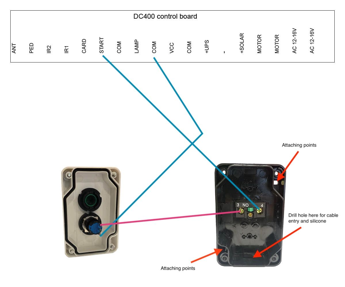
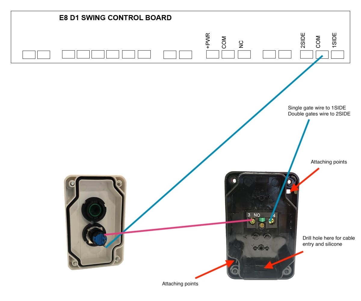
These will wire directly to the main control board, please refer to your user manual or see diagrams below.Unit Attaching Points
We recommend attaching the push button via the attaching points indicated with a red arrow shown in the below images.Please be aware that failure to perform the recommendations above will void your warranty.