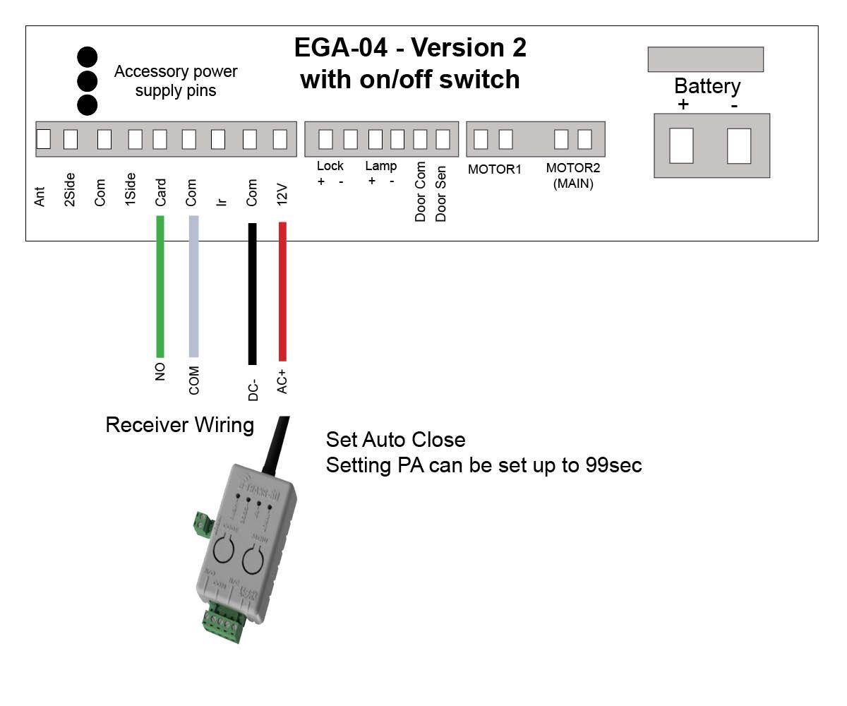
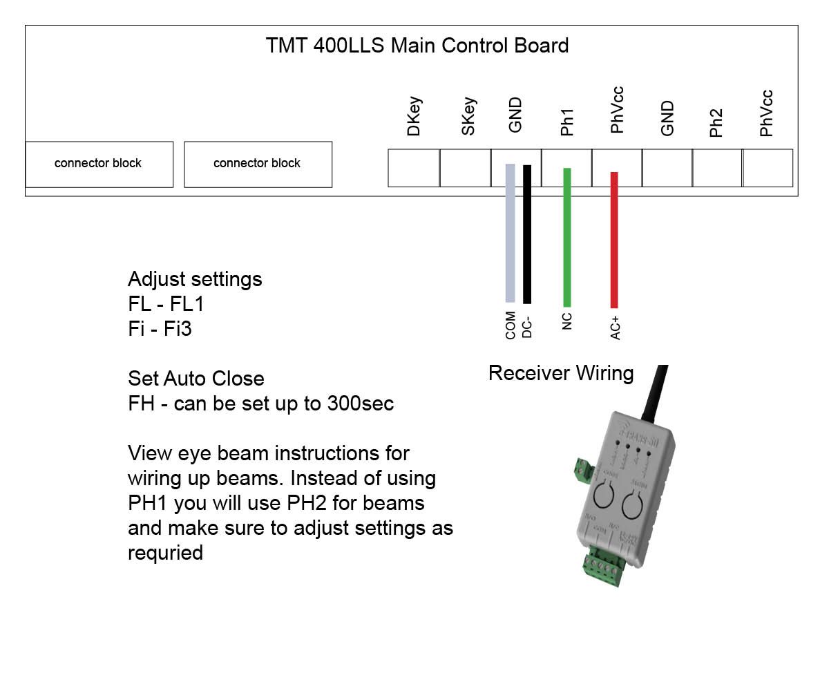
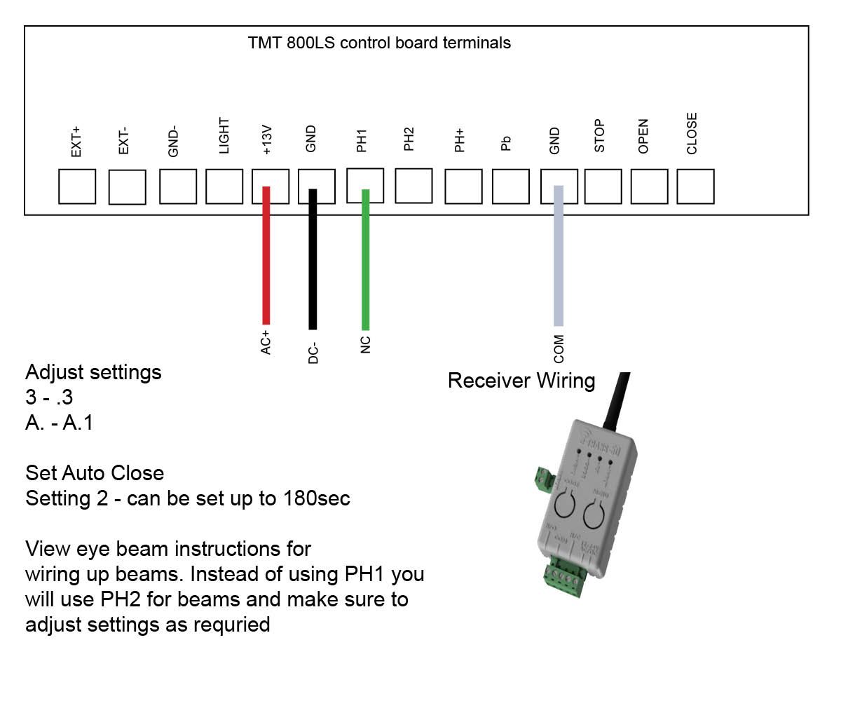
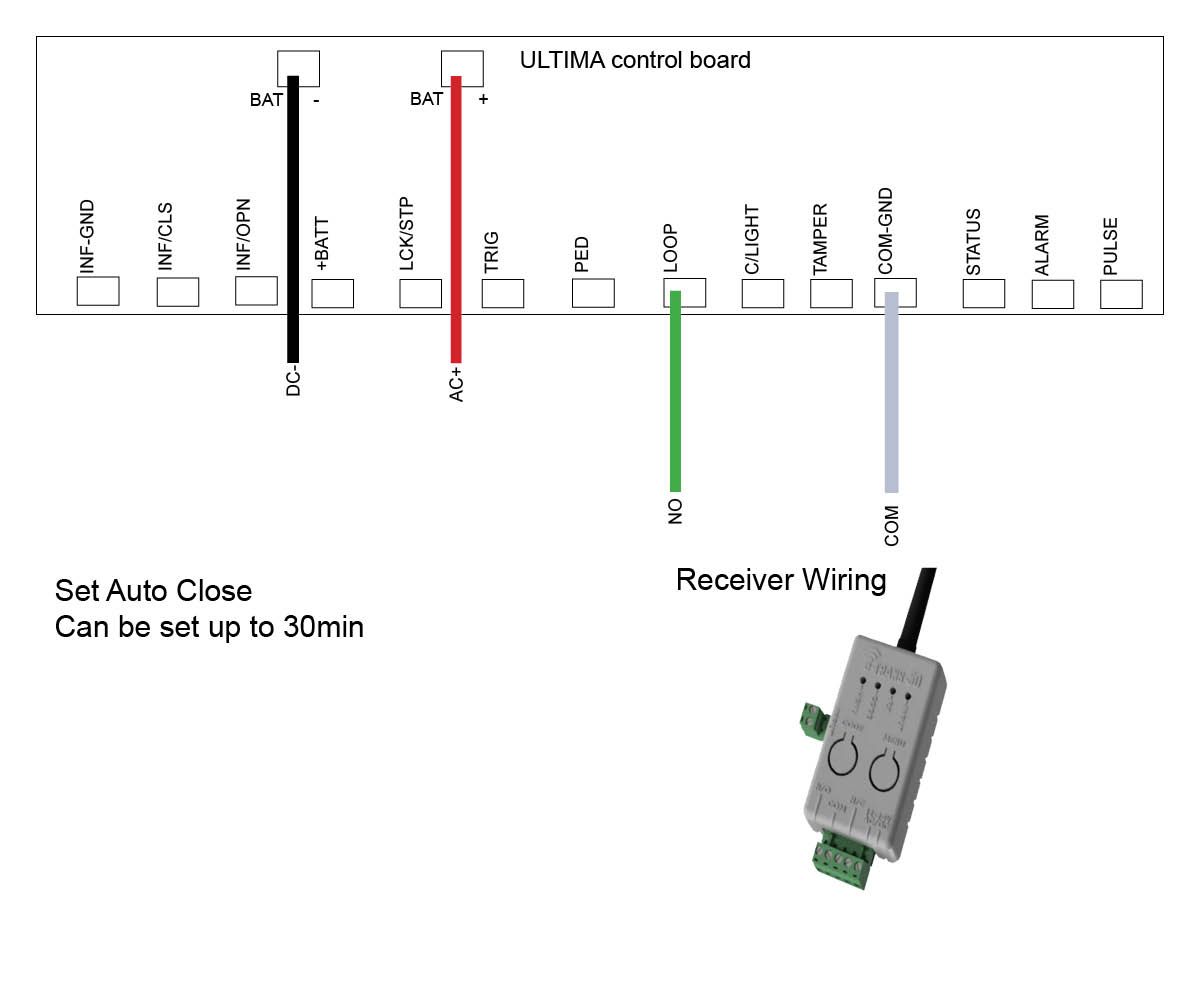
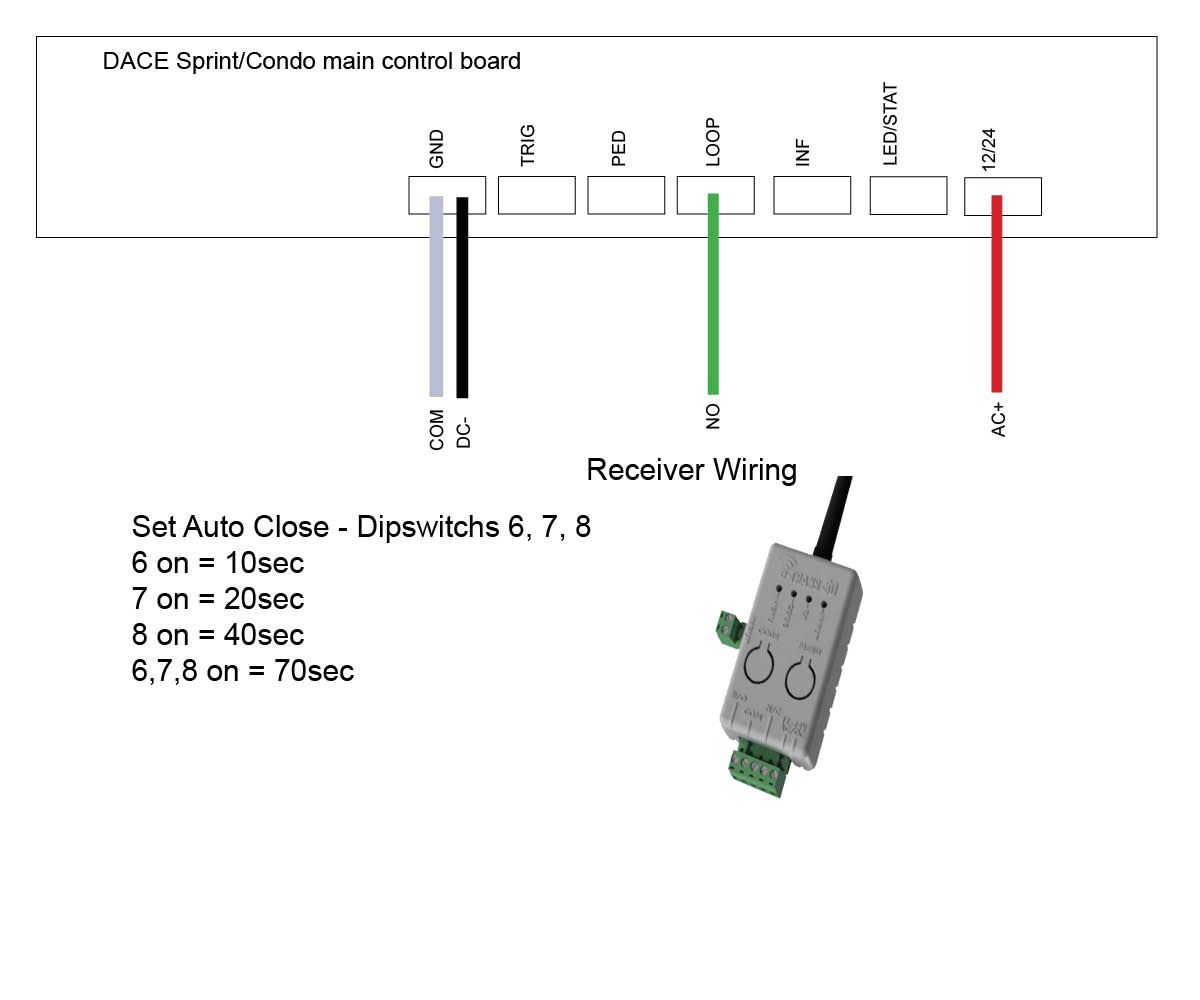
If you're experiencing weak reception, it's likely due to interference affecting the transmission signal. To troubleshoot interference, follow these steps:
- Move the e-Loop and e-Trans closer together (remember to re-calibrate the e-Loop after relocation).
- Disconnect the transceiver from the control board's power source and connect it to an independent power supply (such as a 12V battery).
- If switching to an external power source resolves the issue, the interference is probably coming from your gate controller or connected accessories.
- Reconnect the system without any accessories attached (common interference sources include GSM boards and receivers). If the transceiver now works, reconnect accessories one by one to identify which one is causing the issue.
Once the problematic accessory is found: try powering it from an external source and test the transceiver again. If using external power isn’t an option, place a ferrite bead on the accessory’s power cable—positioned as close to the accessory as possible—to help suppress radiated noise interference.
Note: If reception remains poor, adding an external antenna can enhance the transceiver’s radio performance.Try powering the accessory externally & test transceiver again. If external power is not feasible, clamp a ferrite bead around the accessories power cable as close to the accessory as possible. This will reduce interference from radiated noise traveling via the cable.
Note: If signal strength is still poor, the use of an external antenna can boost radio capabilities.