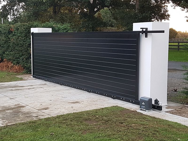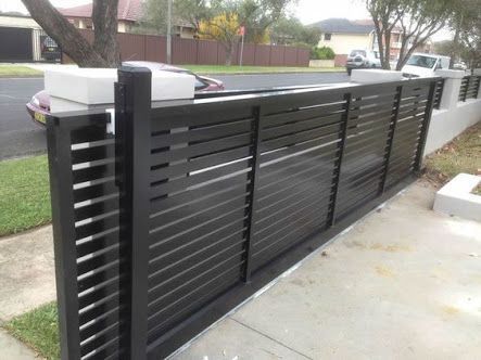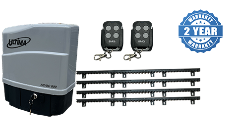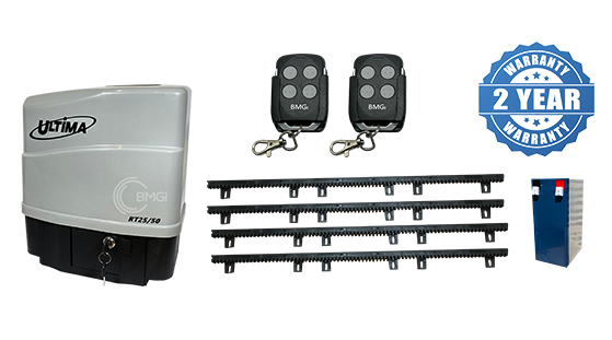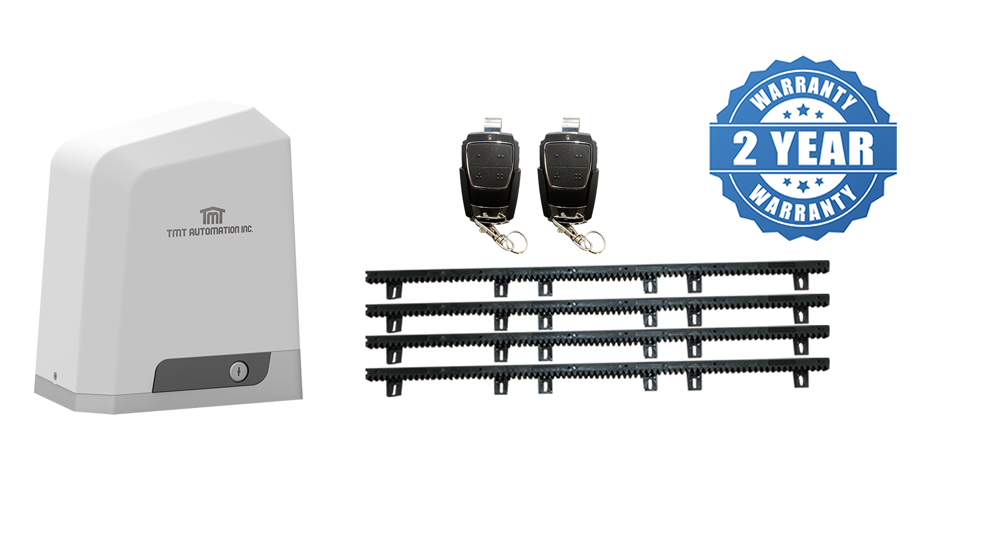
Want to install your own automatic sliding gate? BMGi has all the gear you need to build and install an automatic sliding driveway gate.
Note: The information on this page is intended as a guide only representing a typical installation. Dimensions will vary depending on your gate type and running gear setup.
Questions for you to answer and consider:
- What is the width of the driveway?
- Is there sufficient space adjacent the driveway for the gate to slide back onto when open?
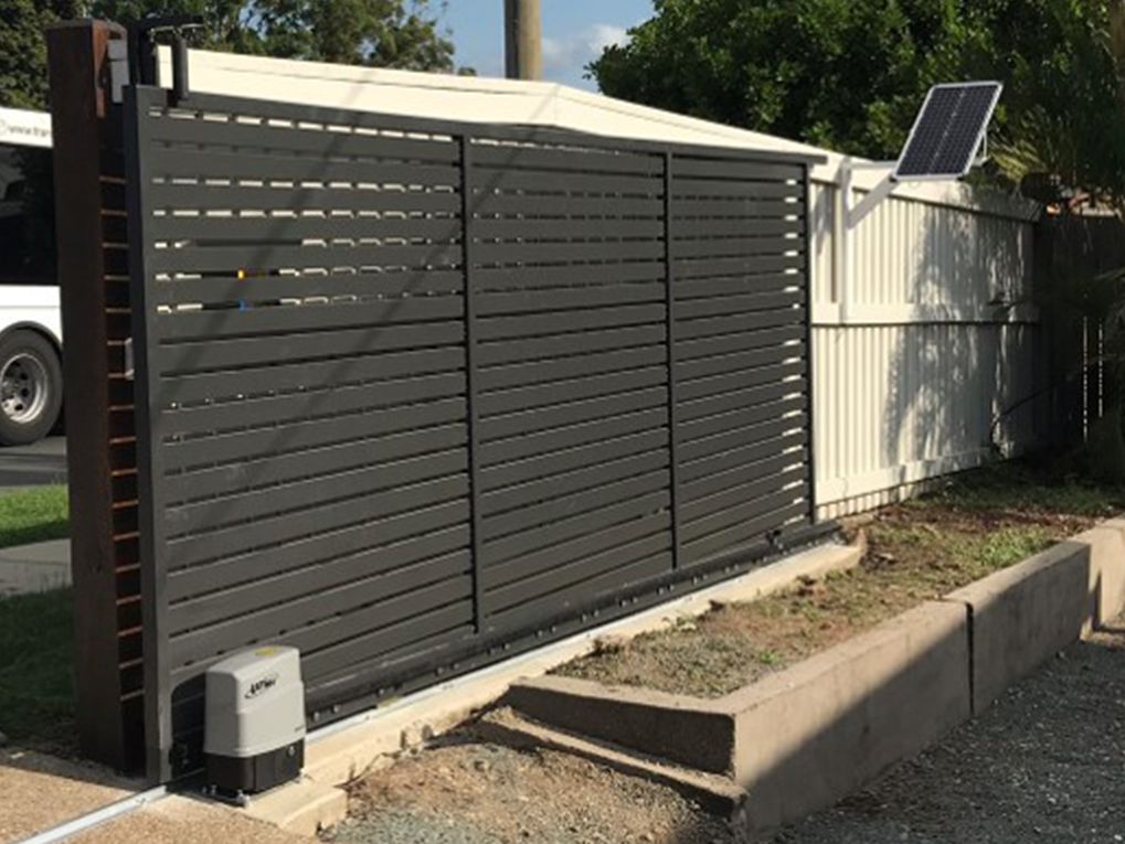
- What type of gate opener will suit my requirements, 240V, DC or solar?
- Is the driveway the only entrance to the property?
If YES - Will a pedestrian gate be required?
If YES - Consider installing a battery backup motor to ensure your gate remains operational if you have a power blackout. - Is there a fall/gradient across the driveway from left to right? I.e. is the ground level?
To workout the fall run a string line that is level across the driveway and check the difference at each end. If you have a significant fall you will need to add a minimum 25% extra in your weight calculations for the motor. - What type of design would you like for your gates?
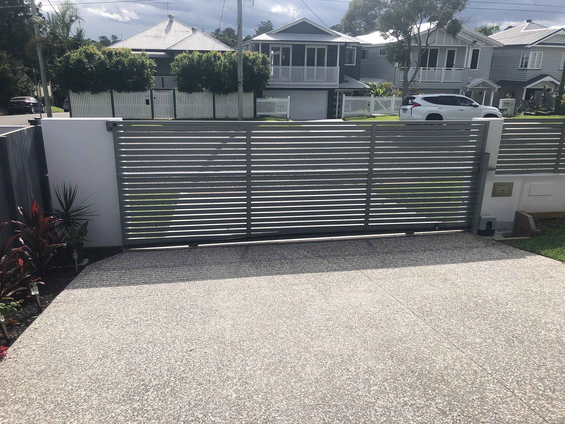
- Estimate the approximate weight of the gate. Take into consideration that with solid gates (sheeted gates you can’t see through) the power needed to drive the gate increases because of the increased weight and wind load (friction) on the gate. Allow a minimum 25% extra in your weight calculations if you choose a gate of this design and location. The average person can lift 70 kgs so 4 people will lift 280kgs. This is a medium gate. Gates over 400kgs are considered heavy and gates under 200kgs are light.
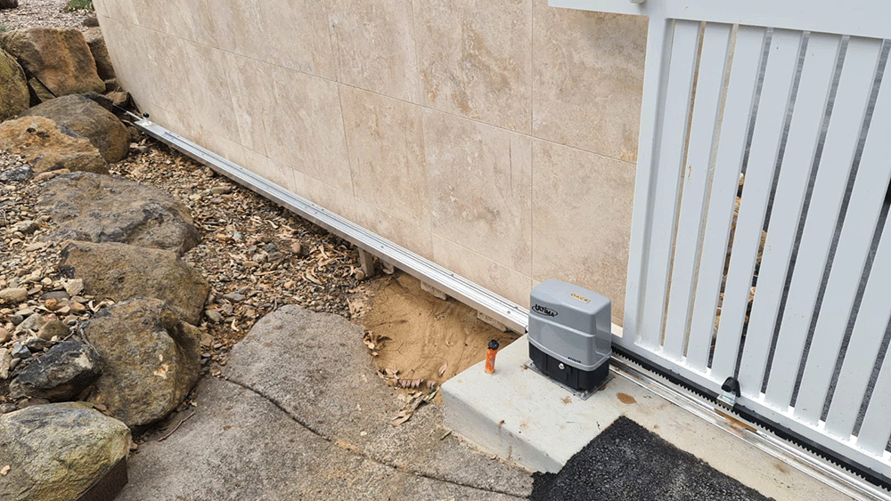
- What surface is the driveway?
The surface needs to be continuous concrete for double the width of the driveway and generally 200-250mm across. The depth of the footing will be dependent on soil conditions and traffic weights. We recommend you place reinforcing rods into the construction across the driveway.
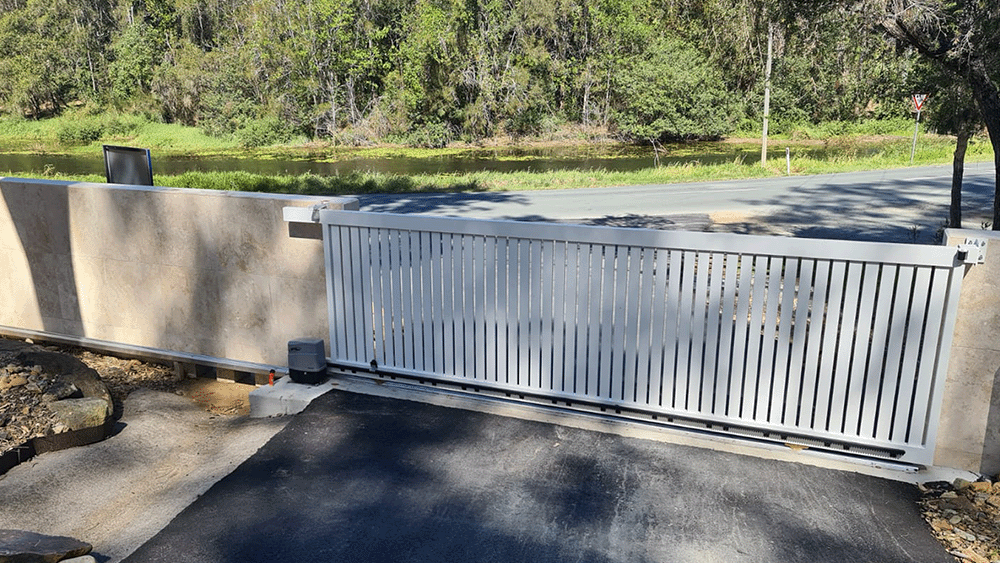
Things to consider when you are having your gate built; Aluminium gates are light weight, strong and will not corrode in harsh conditions such as sea side locations. They are easy to install and will not need expensive heavy duty openers and are easy on the running gear. Steel gates are strong but heavy and need to be zinc coated prior to powder coating if you want them to last as long as alloy.
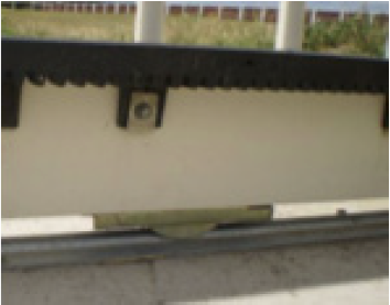
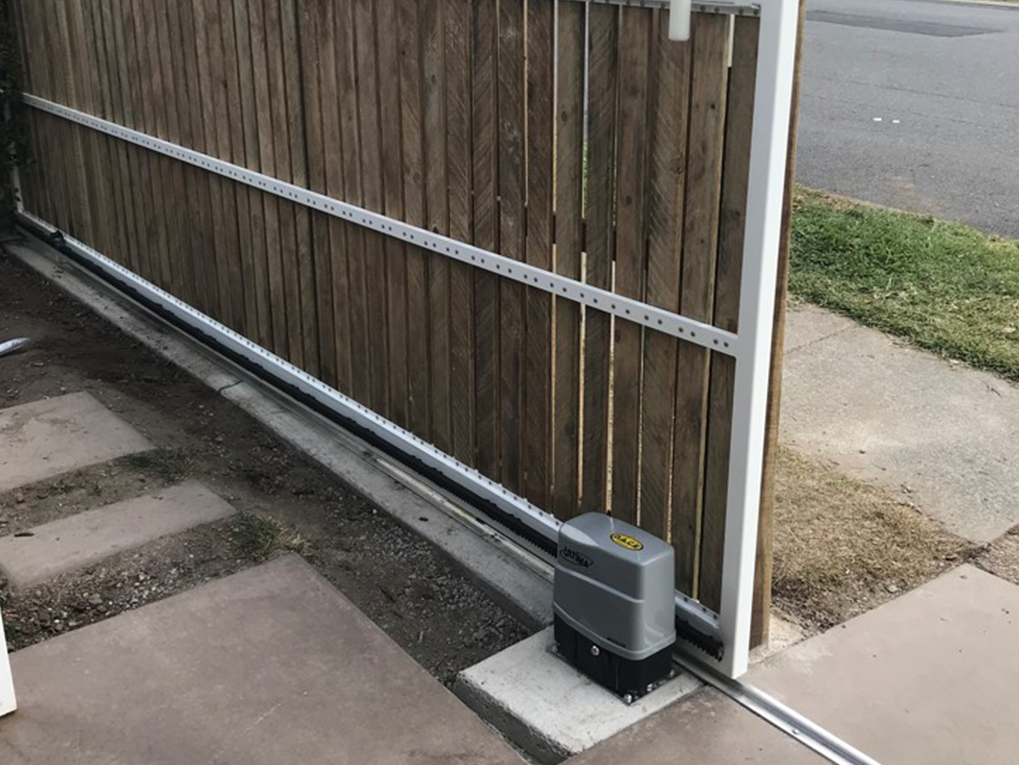
The bottom rail needs to be no less than 75mm high. BMGi gates have a 100mm x 50mm bottom section.
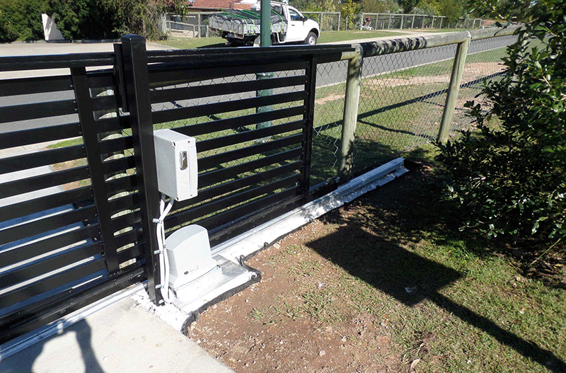
- Support post of no less than 75x75 RHS is required, preferably 100 x 100 and concreted into the ground.
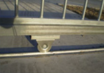
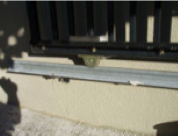
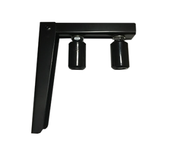
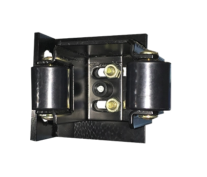
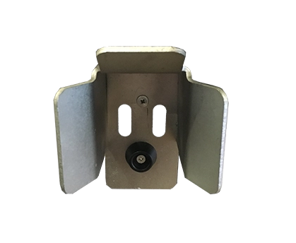
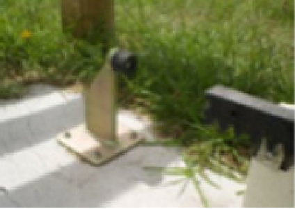
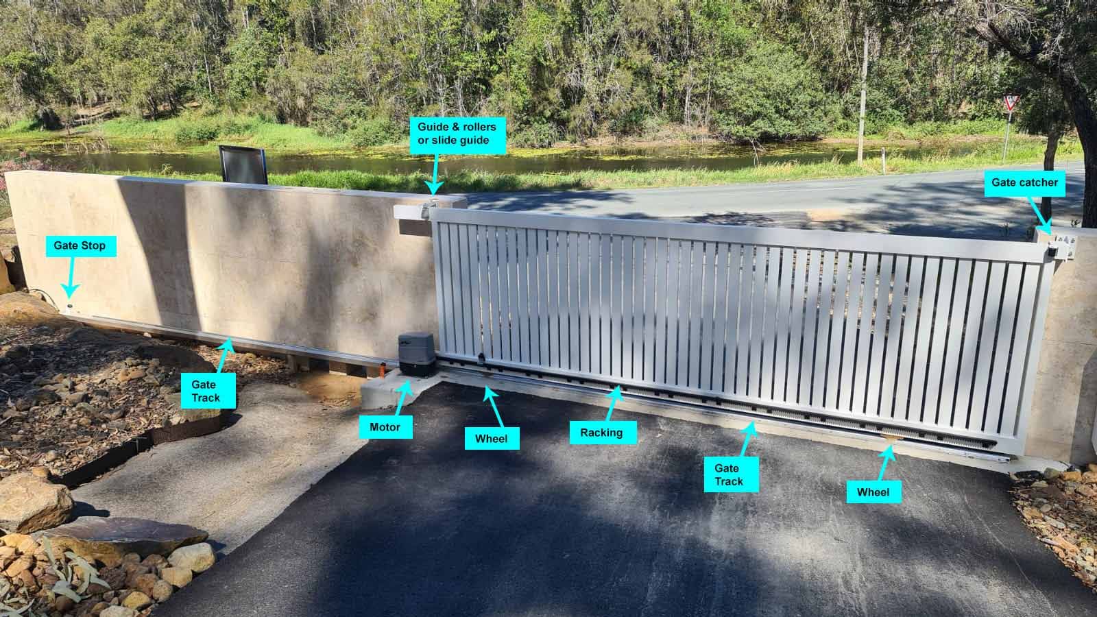
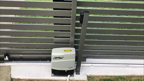
- Ensure a catcher bracket is installed in the closed position and a top guide bracket fitted to the top of the post above your automation motor to hold the gate vertical. This will help prevent it being pushed over. Always install a stopper at the bottom of the gate in the fully open position to prevent over running.
Basically the gate must run well manually before installing your automation. The test we use is that you must be able to open the gate with two fingers while slowly walking (on level ground).
Do you want the gate to automatically close behind you when you drive in or out? All BMGi's auto gate openers have this feature.
If NO - you will press your hand transmitter once to open the gate and then press it again to close it.
If YES - we recommend installing photocells (safety beams) which will prevent the gate closing on obstacles such as your car. A conduit will need to be installed between the motor position and the catcher post or you can run cable through the gate track. If this is not possible we do have wireless safety beams.
How will visitors enter or let you know they have arrived if there is no pedestrian gate?
We recommend BMGi's keypad for the outside of the property and either our standard push button or keyed push button on the inside of the property. All our keypads and push buttons come it a wired setup or wireless setup.
Another solution is to install our wireless intercom which will allow you to speak with the person at the gate and you can either provide them with the keypad number to enter your property or if your remote provides good range you may be able to open the gate from within the house.
Do you need access back out through the gate without your remote control while gardening or walking the dog?
A wired keypad is a good option here as with the entry but a standard push button or keyed push button is also a common addition placed inside your property so that you can press it from the car window.
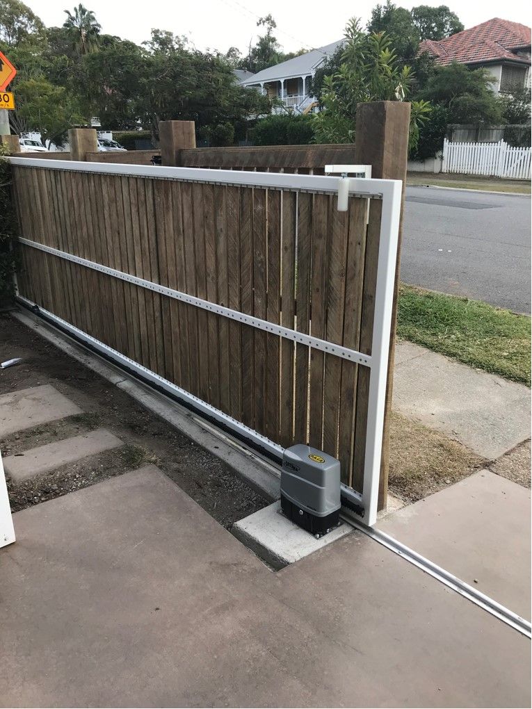
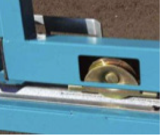
The more time you spend at this stage the less mistakes made and time wasted doing rework, so spend a bit of time getting this part right. Any sliding gate has only a few key parts that need consideration - the track, the gate, guide support post or pier, receiver post or pier.
The automation section has many more considerations but just for the moment let’s concentrate our planning on the basics as they remain constant whether the gate is automated or not.
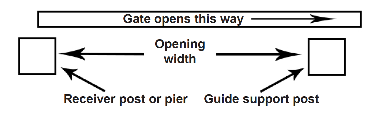
The first thing we need is two definable points to determine our gate opening. You may have existing posts, brick or concrete piers. If not you will need to allow for the installation of posts or piers to act as a receiver on closing and guide support.
If you are installing new posts we would suggest 75mm - 100 mm square as a good size and if concreting into the ground a minimum of 600mm in concrete with legs attached.
Once we have determined our two points we can start to look for and record some information -
- The opening width between our two posts or piers.
- From the opening width we add an extra 100mm to each end of the gate. This will give us our overall frame length.
- Then allow a 300mm tail for the bottom of the gate frame which will allow the motor to sit well away from the driveway.
- Once we have a total gate length (including any tails) we can check to ensure sufficient room to slide the gate open fully without impeding the opening.