TMT Electric Farm Gate Opener
Electric Farm Gate Opener
Double Kit $1495
-
Actuator arm/s
-
Control box
-
Control board
-
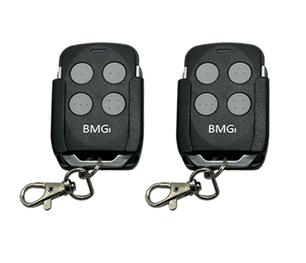
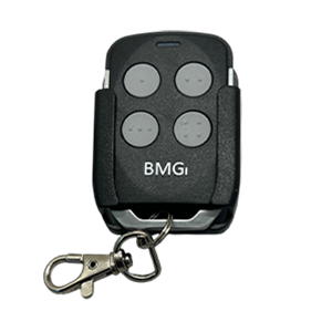
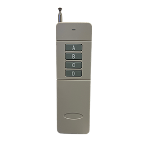
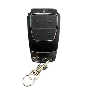
2 x remotes (with 2 free visor/holders)
-
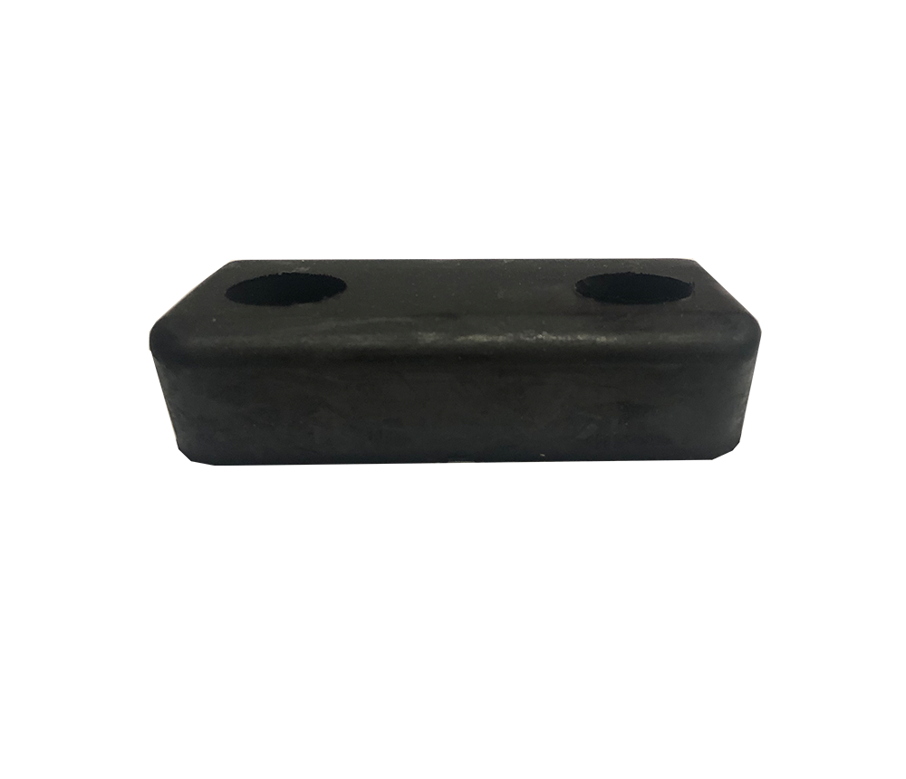
Post/gate brackets and gate stop
-
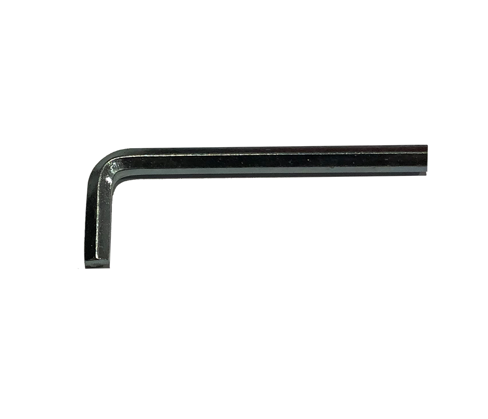
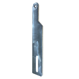
2 x Release keys
-
Warning sign
-
1 x 24Volt Outdoor Transformer
(low voltage cable & connector not supplied) -
Single kit - 2mtrs prewired 7 core arm cable
-
Double kit - 1 @ 2mtrs and 1 @ 12mtrs prewired 7 core arm cable
-
Manual and wiring diagrams
-
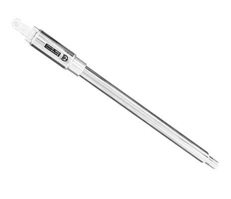
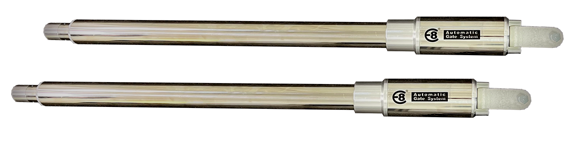
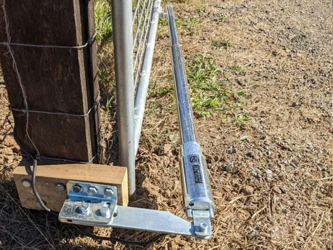
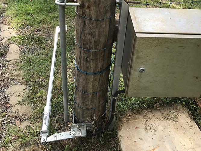
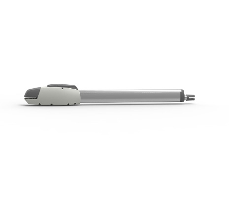 Actuator
 -
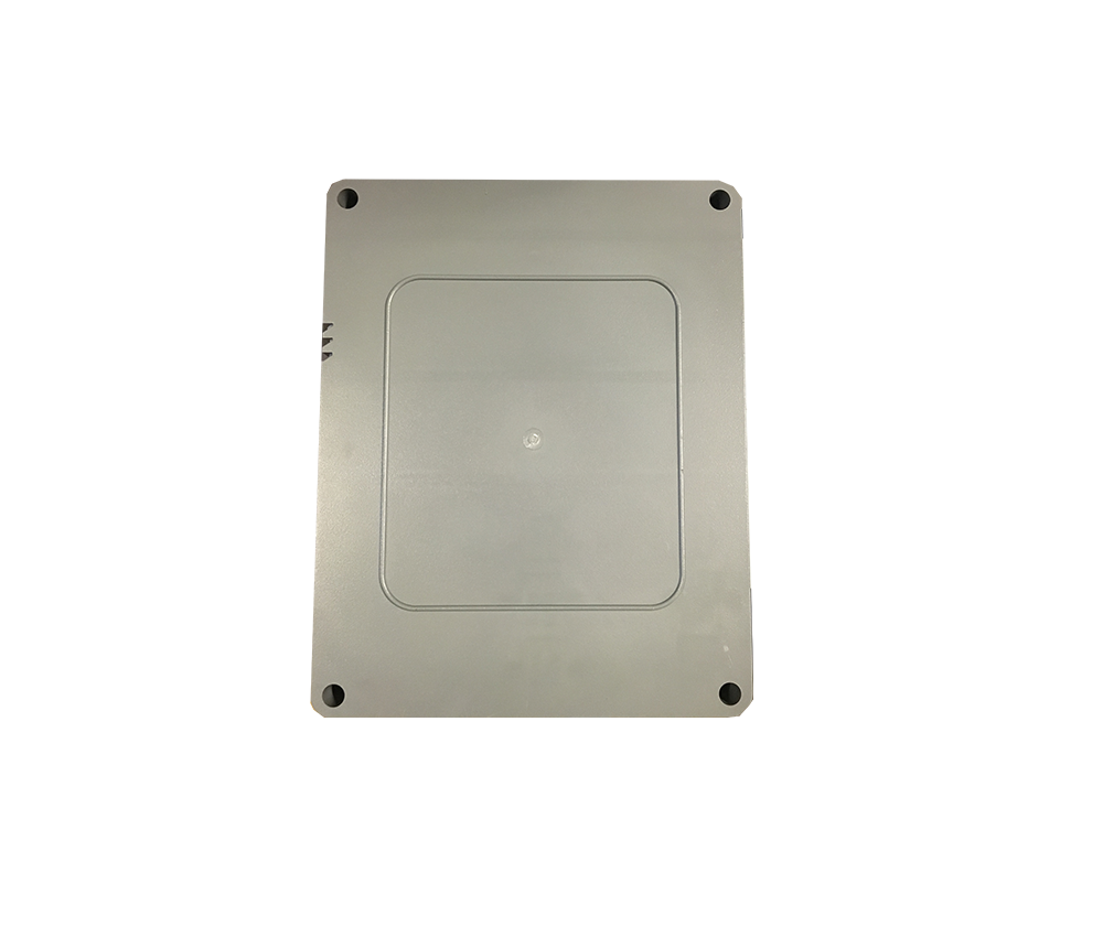
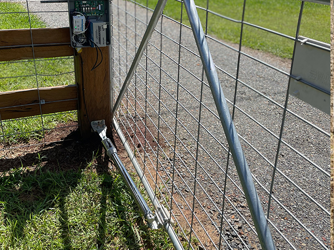
 Control Box
 -
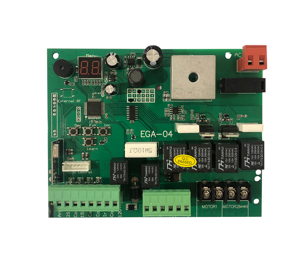
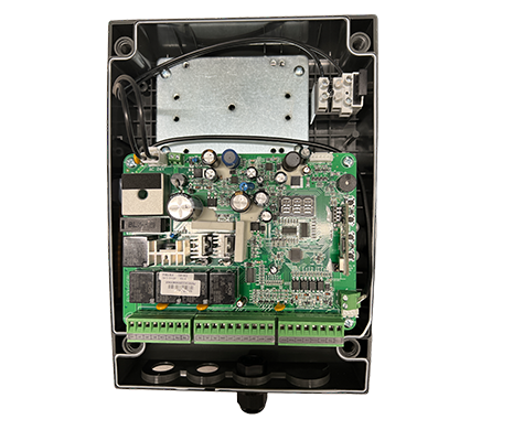 Control Board
 -
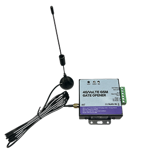
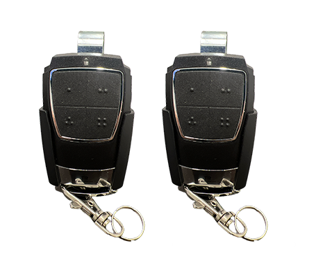 Remotes & Receiver
 -
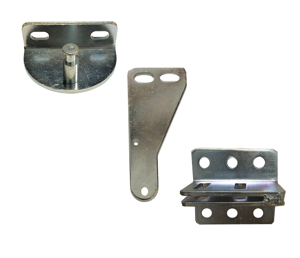
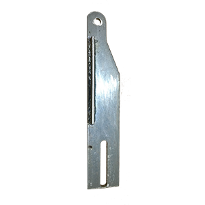
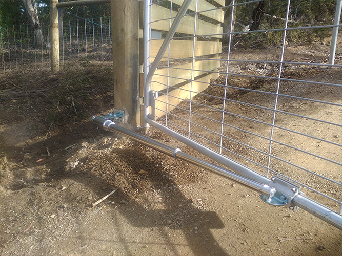
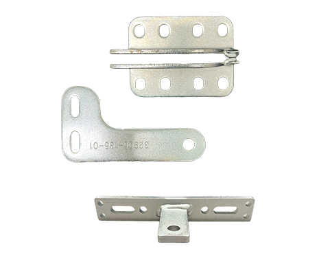 Brackets
 -
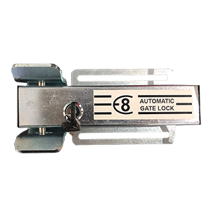
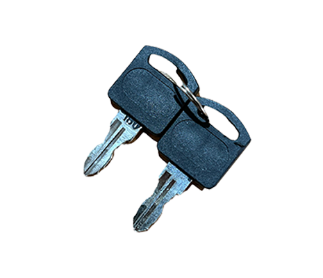 Release Key
 -
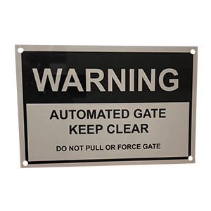 Caution Sign
 -
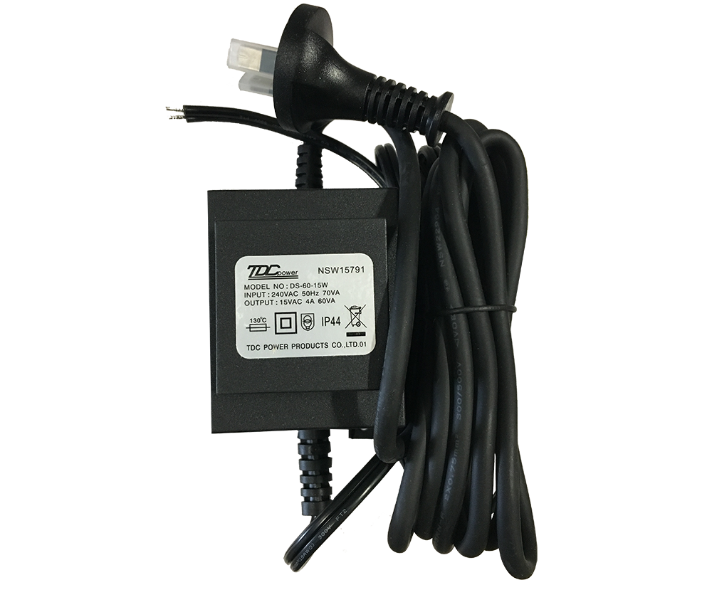 Transformer
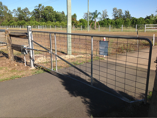
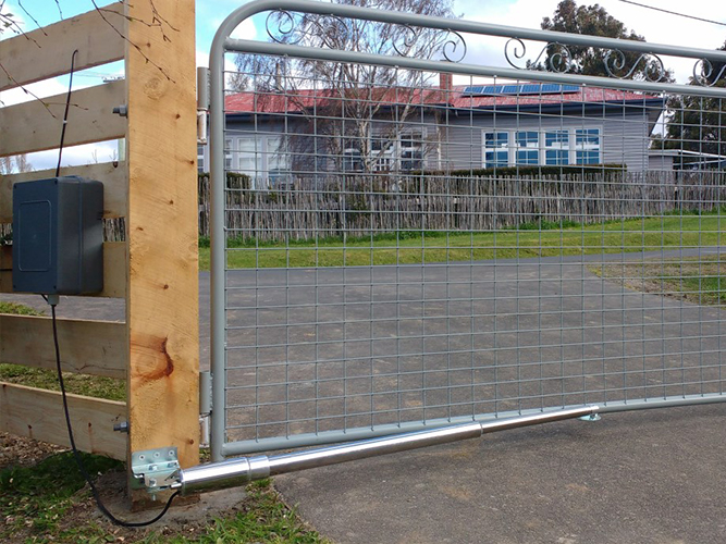
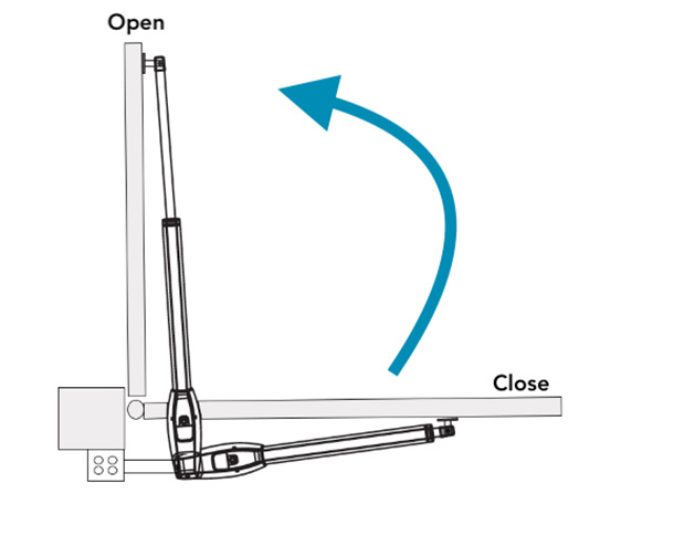
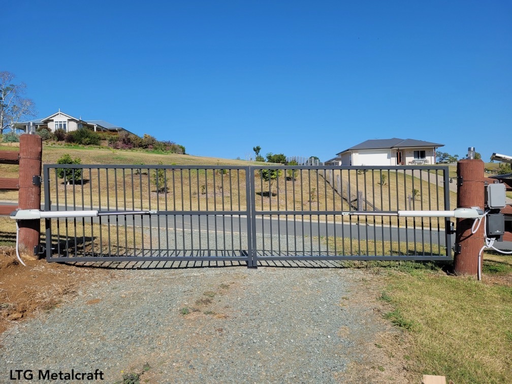
Electric Farm Gates
Available in Single and Double kits
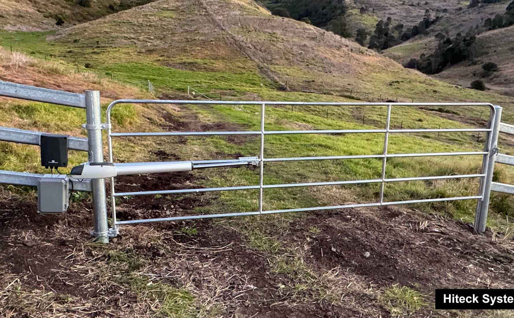
Extra low voltage electric auto gates for farm gates can improve efficiency,
increase security, and make farm management easier and more effective
Are you a farm owner looking to automate your gates? It can be challenging, especially with wide, lightweight, or flexible gate designs. But worry no more — BMGi has the perfect solution for you.
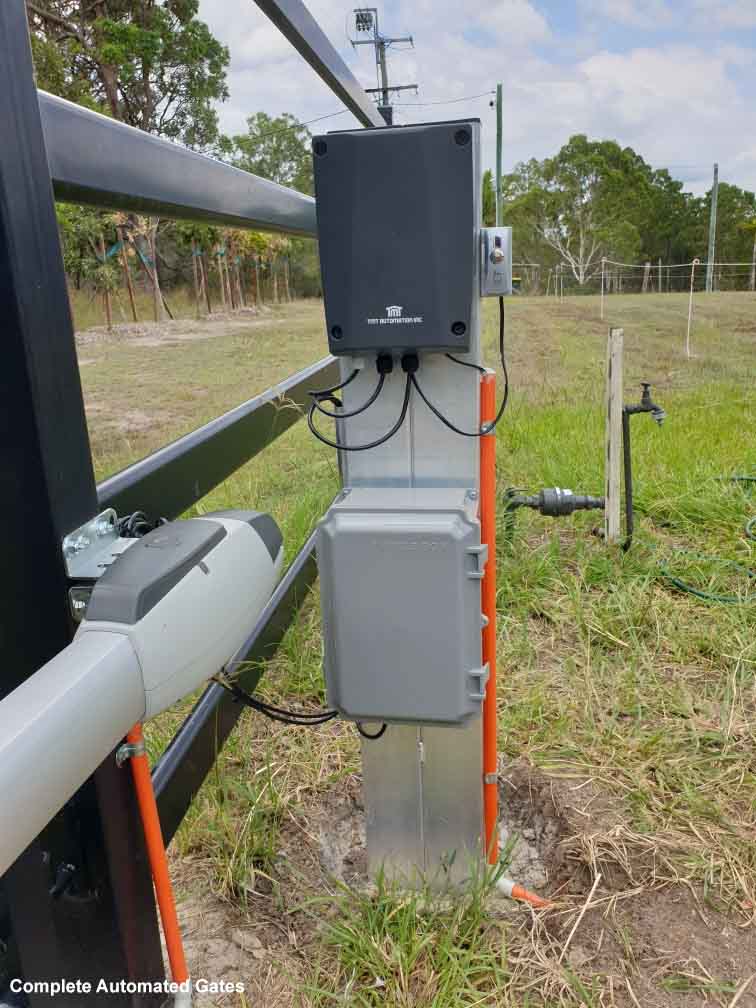
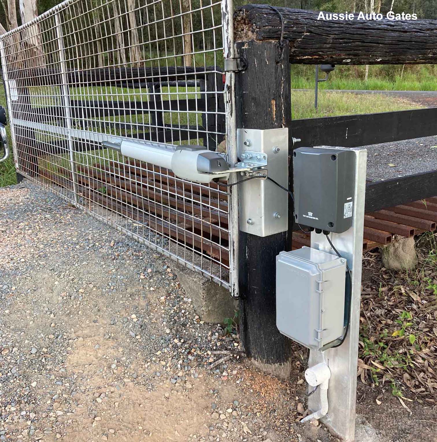
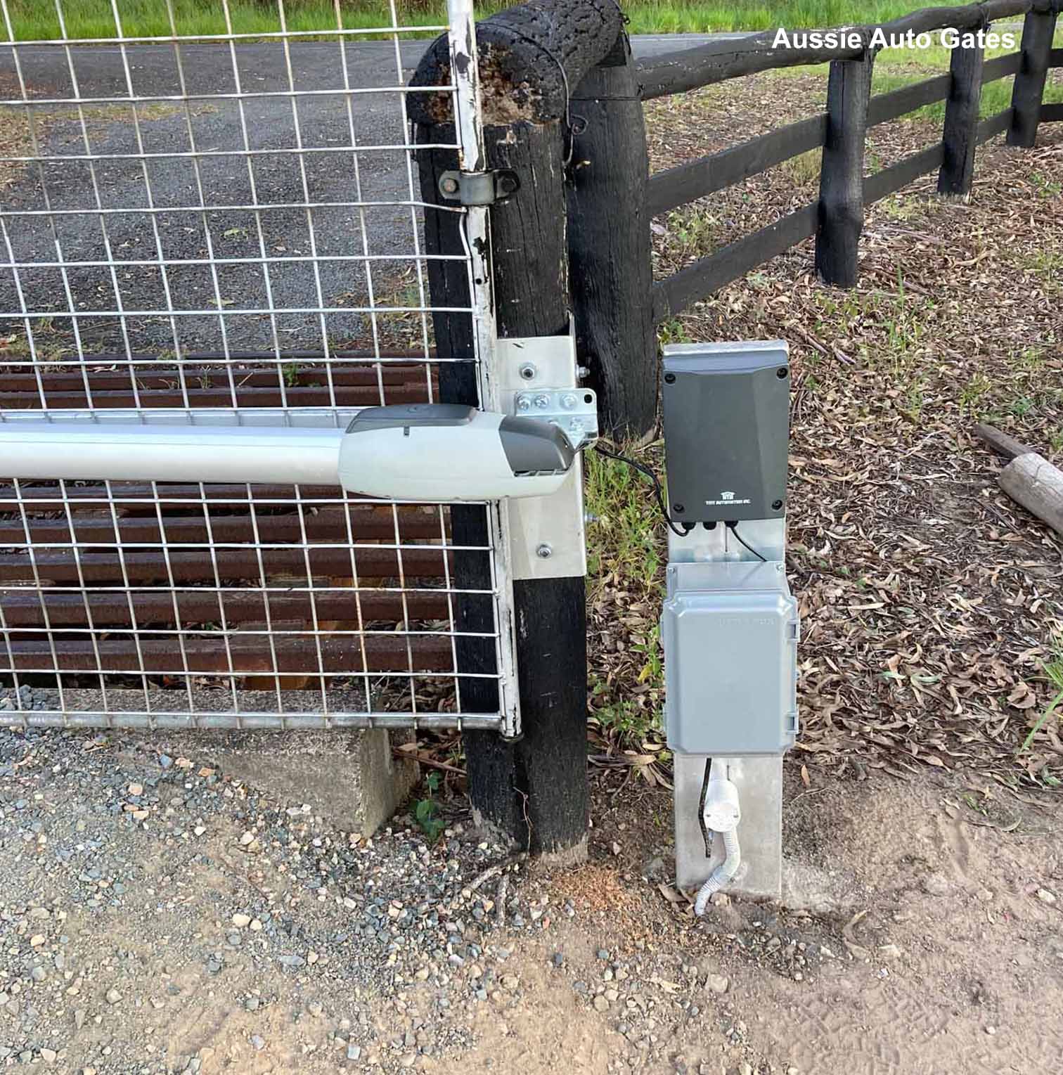
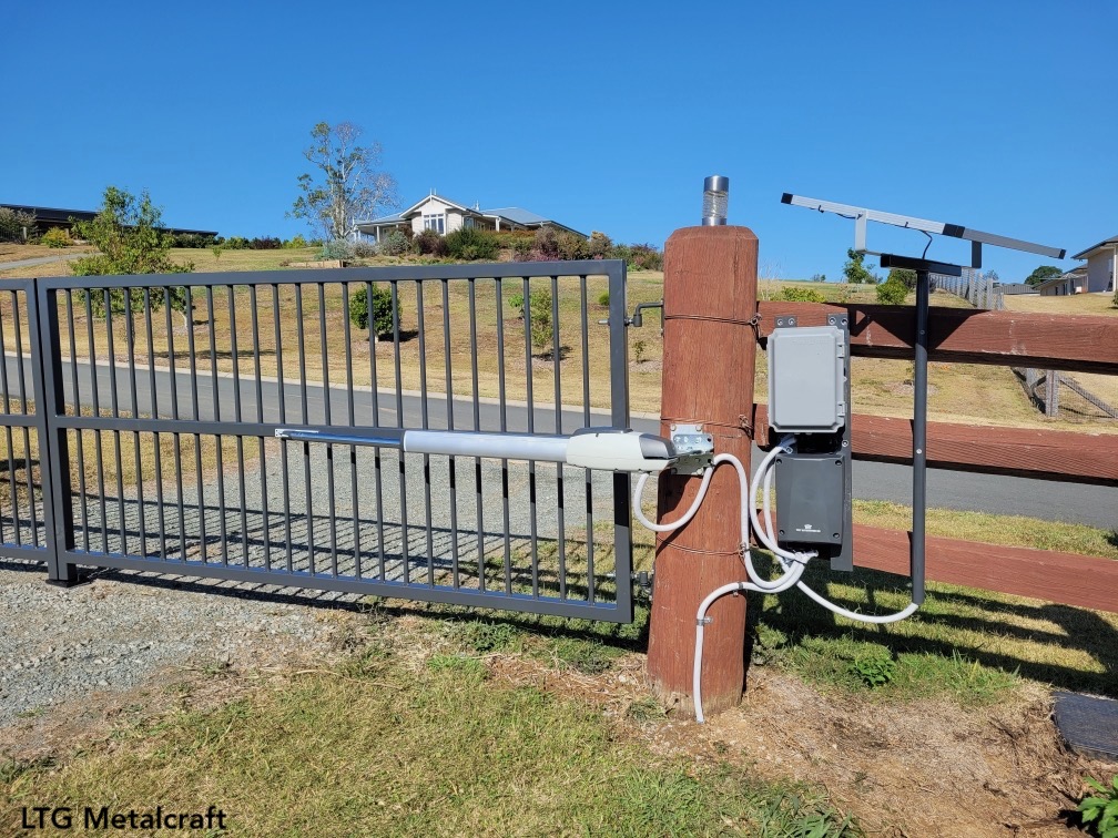
Introducing BMGi’s innovative TMT 400LLS electric gate opener, designed to deliver convenience, reliability, and security while standing up to Australia’s harsh conditions. Our team of experts has spent years refining these kits to ensure long-lasting performance and durability.
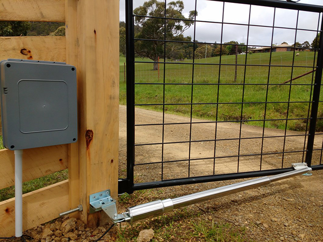
A standout feature is the weatherproof control box, which shields the internal components from rain, dust, and other environmental factors. This means you can rely on consistent operation, even in tough outdoor conditions.
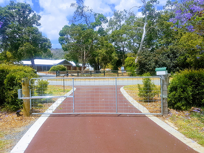
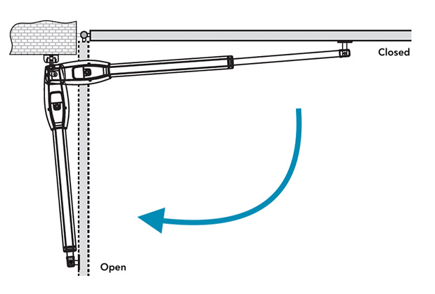
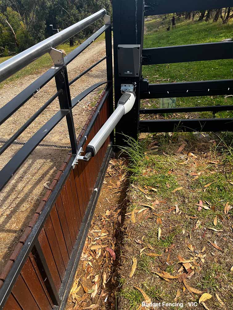
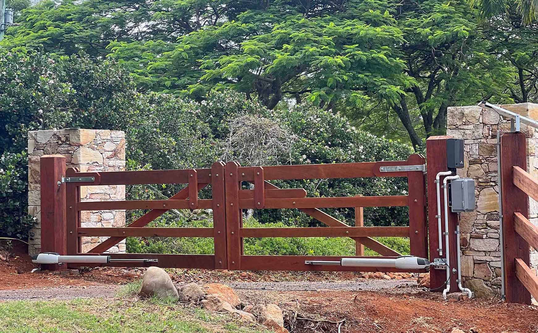
The TMT 400LLS is engineered to work seamlessly with farm gates up to 16ft or 5 metres, and every component has been carefully designed for optimal performance. Best of all, it’s available as a DIY kit, making it simple to automate almost any properly hung swing gate with ease.
Thousands of farm owners across Australia have already chosen BMGi’s gate opener kits for their dependability and ease of use. With BMGi, you can enjoy the convenience of automated access and the peace of mind that comes with a trusted, low-maintenance system.
TMT 400LLS gate opener is a game changer for farm owners who want to automate their gates. Built tough for Australian conditions and designed for straightforward DIY installation, it offers a reliable, secure, and proven solution for automated farm gates.
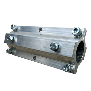
TMT Round Gate Bracket
$65/ea
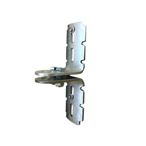
Round Post Bracket
$35/pr
TMT Outward Opening Bracket
$35/ea


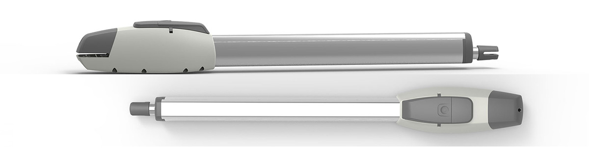
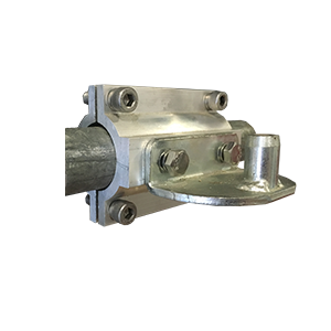
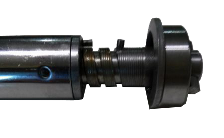
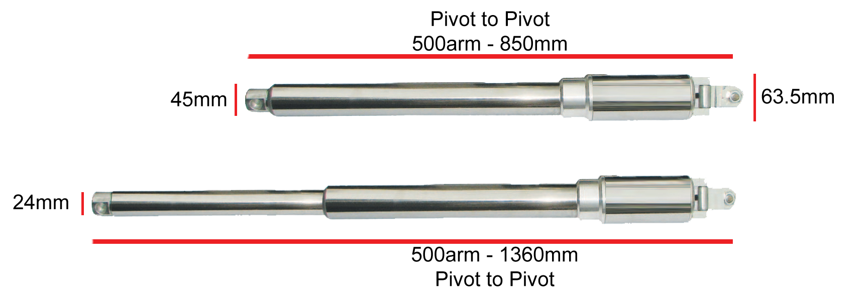
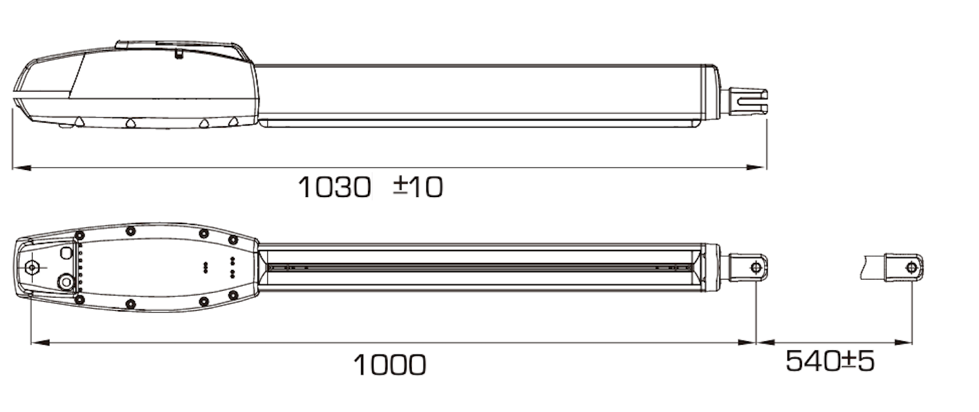
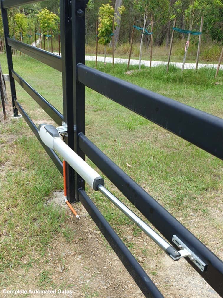
Heavy Duty Linear Actuator
Featuring a die cast aluminium motor cover that provides resistance to critical environmental factors.
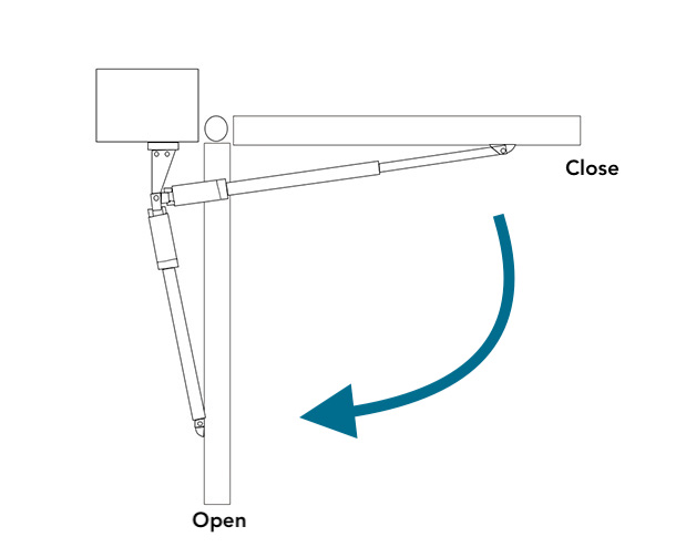
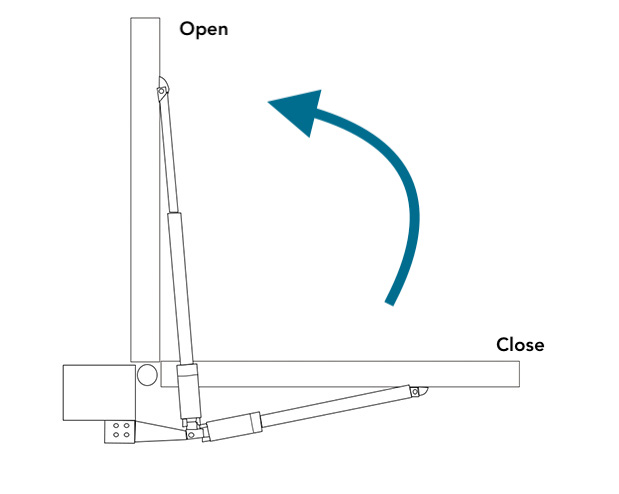
Universal left and right side installation.
Simple low voltage system making this motor a breeze to install for all skill levels.
The system can handle light to heavy weight gates up to 5m in length.
-
Gear Type: Metal screw drive
-
Motor Voltage: 24VDC
-
Limits: Can setup on either limits or overcurrent
-
Manual override: Key
-
Duty Cycle: 50%
-
Maximum stroke: 500mm
-
Gate Size: Max 5mtrs - Min 1.4mtrs
-
Gate weight: 450kgs @ 3mtrs - 300kgs @ 5mtrs
-
Adjustable force settings through the digital menu
-
Adjustable auto close up to 5 minutes
-
Free exit input
-
Party mode - allows you to press a button on your remote to override the auto close setting
-
Adjustable ramp up and ramp down - now you can dictate when the ram with slow down
-
On board receiver to reduce setup time, no more wiring in external receivers
-
Adjustable speed
-
Tunes up to 80 remotes
-
Energy efficient board
-
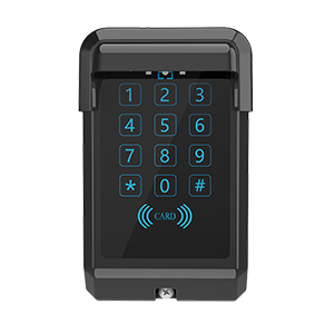
Wireless keypad tunes to onboard receiver
-
Kit setup using overcurrent or limit stops
-
Adjustable time between main gate and slave gate for double swing kits which is useful for units with gate locks or for units that require 1 gate to make it closed first
Solar Powered Farm Gates - TMT Setups


Read more: TMT Electric Farm Gate Opener
- Hits: 8641