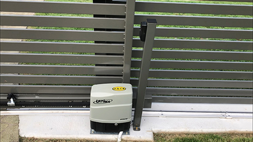
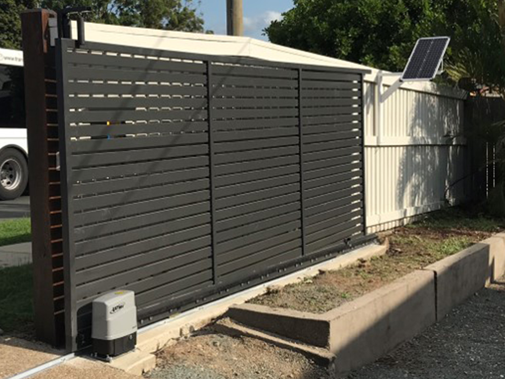
Why the Dace Ultima is perfect for solar applications
The Ultima series of motors has been designed with solar application as a driving focus. When you decide on a solar powered gate opener, it’s important to look for a motor kit with the following:
Energy efficient control board to ensure a long standby time during poor weather conditions.
Adequate deep cycle battery size to ensure the motor will still be operating during prolonged poor weather conditions.
Adequate solar panel size to ensure the battery is receiving enough charge.
Energy Saving Modes
The Ultima series has 3 energy saving modes which can be activated in the ‘Energy Saving’ icon through the easy to use joystick and large LCD screen. Light sleep mode, Medium sleep mode and Deep sleep mode can be selected. Deep sleep mode will give you up to 16 days of standby time when being powered by a fully charged 12v14ah battery.
Deep Cycle Battery
It’s important to use a Deep cycle battery with any solar gate opener kit. A deep cycle battery handles consistent cycling (charging and discharging) which is constantly happening with all solar powered gate openers. BMGi uses and recommends a high quality 12v14ah deep cycle battery to provide reliable power.
Solar Panel Efficiency
BMGi only uses monocrystalline solar panels with any solar kit sold. Monocrystalline solar panels are more efficient, provide a long life span and have a high efficiency level during hot days. A 45 watt monocrystalline solar panel is included in our solar powered Ultima gate operator kit. BMGi recommends a minimum of a 40 watt solar panel due to the higher charging rate that solar units require.
When it comes to solar powered gate openers, the Ultima series has you covered.
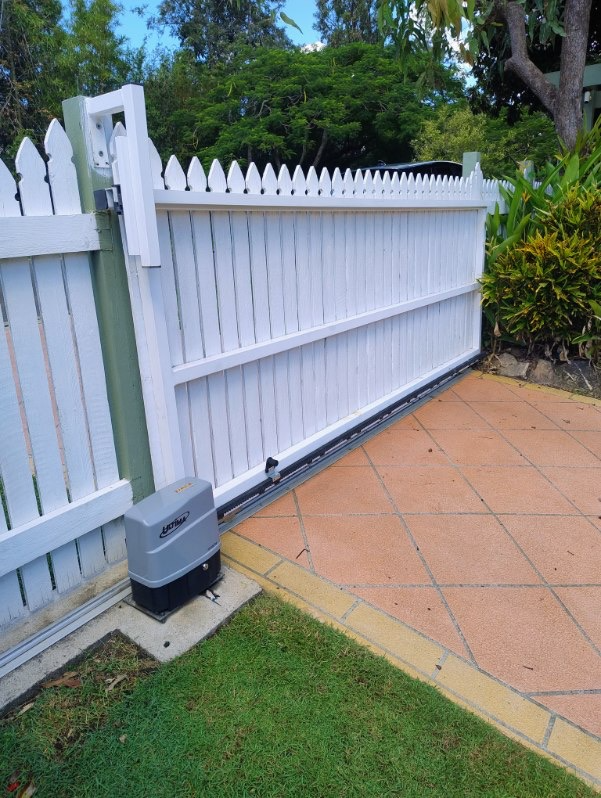
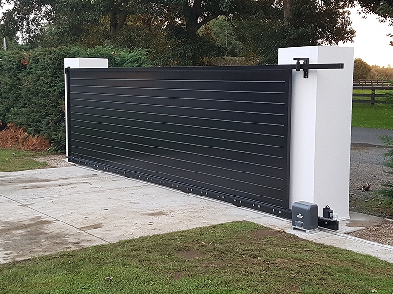
Why the Dace Ultima Slide Gate Opener is Ideal for DIY Users and Professional Installers
When it comes to sliding gate openers, the DACE Ultima series stands out as a top choice for both DIY enthusiasts and professional installers across Australia. Renowned for its cutting-edge technology, sleek design, and unparalleled performance, the Ultima series offers versatile solutions for residential and light commercial applications. Whether you’re automating a gate in Brisbane, Sydney, Melbourne, Adelaide, Perth, Darwin, or Tasmania, BMGi’s DACE Ultima slide gate motors deliver reliability, speed, and ease of use. With Australia-wide shipping, BMGi ensures your gate automation needs are met with precision and quality.
Why Choose the DACE Ultima Series?
Manufactured in South Africa, the DACE Ultima series combines advanced gate automation features with robust construction, making it ideal for a wide range of setups. From simple residential gates to complex high-traffic installations, the Ultima series offers three models tailored to specific needs:
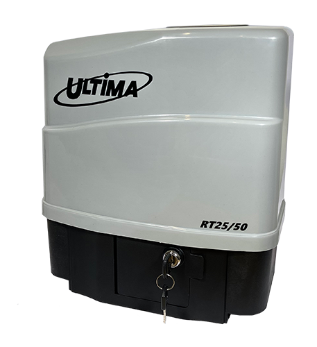
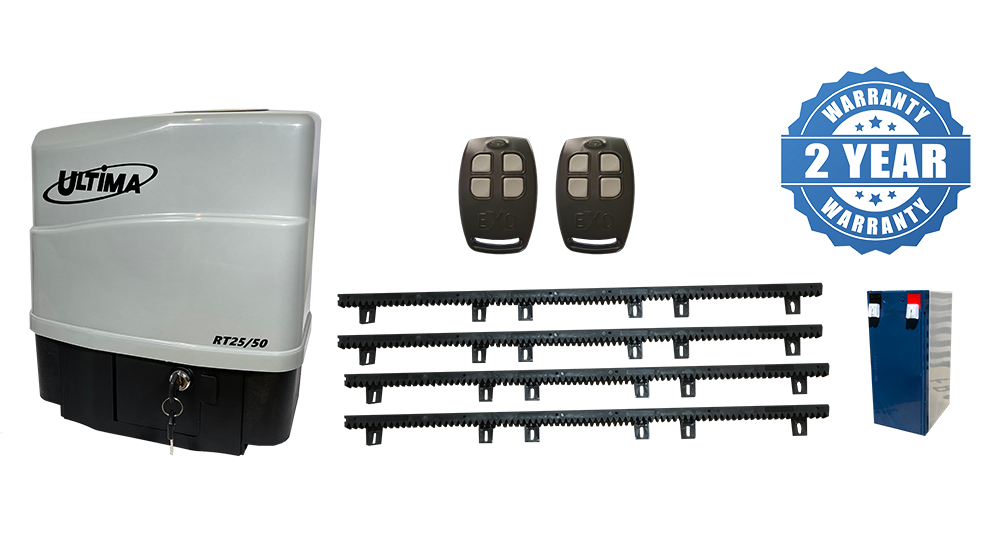
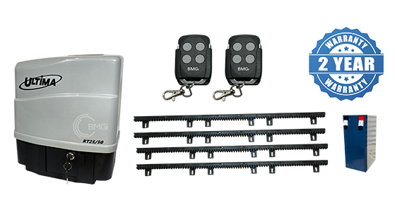
DACE Ultima RT25/50: Designed for regular-traffic residential properties, delivering class-leading speed.
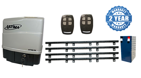
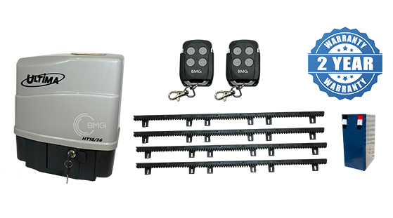
DACE Ultima HT18/36: Perfect for high-traffic residential or light commercial applications.
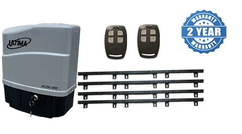
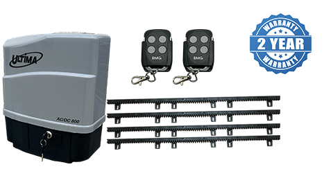
DACE Ultima ACDC 800: Built for high-traffic residential gates, with optional battery backup for uninterrupted operation.
Each model is packed with innovative features, including adjustable speed settings, a user-friendly interface, and safety enhancements, making the Ultima series a favorite among DIY users and professional installers alike.
Unmatched Speed with the DACE Ultima RT25/50
The DACE Ultima RT25/50 sets the benchmark for speed in its class, capable of reaching up to 50 meters per minute. For a standard 4-meter gate, this translates to an opening time of just under 5 seconds—perfect for properties on busy roads or households where quick gate closure is essential to keep pets safe. This high-speed performance ensures seamless access without compromising safety, as the system requires safety beams to achieve maximum closing speeds. Whether you’re in Melbourne or Perth, the Ultima RT25/50 delivers rapid, reliable gate operation for residential applications.
Customisable Speed with the Ultima Navigation Screen
One of the standout features of the DACE Ultima series is its intuitive LCD navigation screen paired with an easy-to-use joystick. This user-friendly interface allows both DIY users and professionals to fine-tune gate settings with ease. If the default speed of 50 meters per minute feels too fast for your needs, the “Run Profile” setting lets you adjust both opening and closing speeds. You can set opening speeds up to 50 meters per minute for quick access and reduce closing speeds to as low as 12 meters per minute for enhanced safety. This flexibility ensures the Ultima series adapts to your specific requirements, whether you’re automating a gate in Sydney or Adelaide.
DACE Ultima HT18/36: High-Traffic Performance
For properties with frequent gate use, the DACE Ultima HT18/36 is the go-to choice. Designed for high-traffic residential or light commercial applications, this model offers robust performance with speeds up to 18 meters per minute. Its durable steel internal gear and battery-operated design ensure reliable operation, even during power outages, making it ideal for busy environments in Brisbane or Darwin.
DACE Ultima ACDC 800: Power and Versatility
The DACE Ultima ACDC 800 is engineered for high-traffic residential gates, supporting up to 800 kg and 20 meters in length. With a maximum speed of 30 meters per minute and an optional battery backup, it’s perfect for users seeking both power and reliability. Whether you’re in Tasmania or Queensland, this model delivers consistent performance for demanding applications.
BMGi is your trusted source for DACE Ultima slide gate openers, offering expert advice and Australia-wide shipping. Our motors are designed for easy installation, making them a favorite for DIY enthusiasts, while their advanced features meet the demands of professional installers. With safety features like collision sensing, pedestrian mode, and party mode, plus support for up to 1024 remotes, the Ultima series ensures convenience and security.
Ready to upgrade your gate automation? Contact BMGi today to explore the DACE Ultima series and find the perfect sliding gate motor for your property. From class-leading speed to customizable settings, the Ultima series has it all.
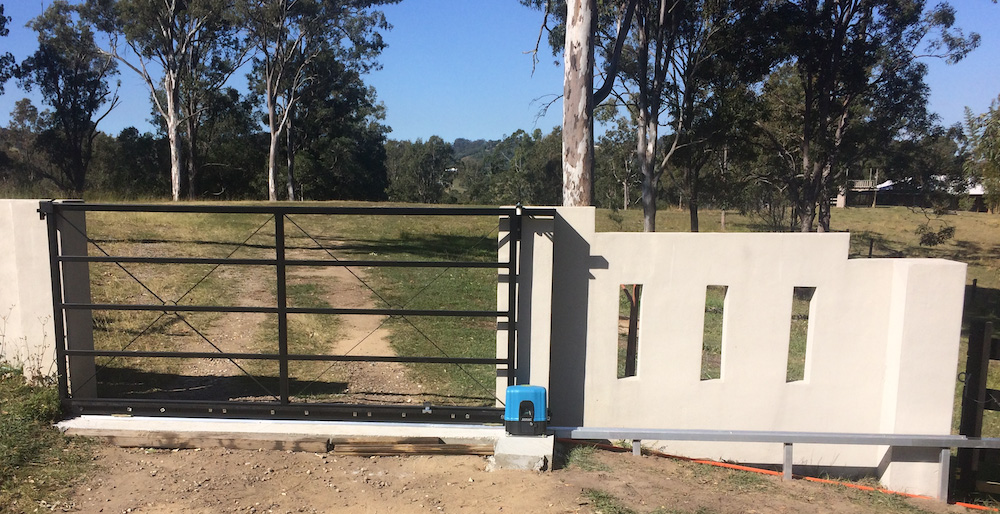
Want to install your own automatic sliding gate? BMGi has all the gear you need to build and install an automatic sliding driveway gate.
Note: The information on this page is intended as a guide only representing a typical installation. Dimensions will vary depending on your gate type and running gear setup.
Questions for you to answer and consider:
What is the width of the driveway?
Is there sufficient space adjacent the driveway for the gate to slide back onto when open?
What type of gate opener will suit my requirements, 240V, DC or solar?
Is the driveway the only entrance to the property? If YES - Will a pedestrian gate be required? If YES - Consider installing a battery backup motor to ensure your gate remains operational if you have a power blackout.
Is there a fall/gradient across the driveway from left to right? I.e. is the ground level? To workout the fall run a string line that is level across the driveway and check the difference at each end. If you have a significant fall you will need to add a minimum 25% extra in your weight calculations for the motor.
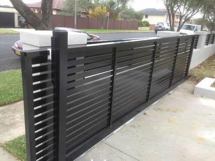
What type of design would you like for your gates?
Estimate the approximate weight of the gate. Take into consideration that with solid gates (sheeted gates you can’t see through) the power needed to drive the gate increases because of the increased weight and wind load (friction) on the gate. Allow a minimum 25% extra in your weight calculations if you choose a gate of this design and location. The average person can lift 70 kgs so 4 people will lift 280kgs. This is a medium gate. Gates over 400kgs are considered heavy and gates under 200kgs are light.
What surface is the driveway? The surface needs to be continuous concrete for double the width of the driveway and generally 200-250mm across. The depth of the footing will be dependent on soil conditions and traffic weights. We recommend you place reinforcing rods into the construction across the driveway.
Things to consider when you are having your gate built; Aluminium gates are light weight, strong and will not corrode in harsh conditions such as sea side locations. They are easy to install and will not need expensive heavy duty openers and are easy on the running gear. Steel gates are strong but heavy and need to be zinc coated prior to powder coating if you want them to last as long as alloy.
The bottom rail needs to be no less than 75mm high. BMGi gates have a 100mm x 50mm bottom section.
Support post of no less than 75x75 RHS is required, preferably 100 x 100 and concreted into the ground.
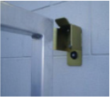
Ensure a catcher bracket is installed in the closed position and a top guide bracket fitted to the top of the post above your automation motor to hold the gate vertical. This will help prevent it being pushed over. Always install a stopper at the bottom of the gate in the fully open position to prevent over running.
Basically the gate must run well manually before installing your automation. The test we use is that you must be able to open the gate with two fingers while slowly walking (on level ground).
Do you want the gate to automatically close behind you when you drive in or out? All BMGi's auto gate openers have this feature. If NO - you will press your hand transmitter once to open the gate and then press it again to close it. If YES - we recommend installing photocells (safety beams) which will prevent the gate closing on obstacles such as your car. A conduit will need to be installed between the motor position and the catcher post or you can run cable through the gate track. If this is not possible we do have wireless safety beams.
How will visitors enter or let you know they have arrived if there is no pedestrian gate? We recommend BMGi's keypad for the outside of the property and either our standard push button or keyed push button on the inside of the property. All our keypads and push buttons come it a wired setup or wireless setup. Another solution is to install our wireless intercom which will allow you to speak with the person at the gate and you can either provide them with the keypad number to enter your property or if your remote provides good range you may be able to open the gate from within the house.
Do you need access back out through the gate without your remote control while gardening or walking the dog? A wired keypad is a good option here as with the entry but a standard push button or keyed push button is also a common addition placed inside your property so that you can press it from the car window.
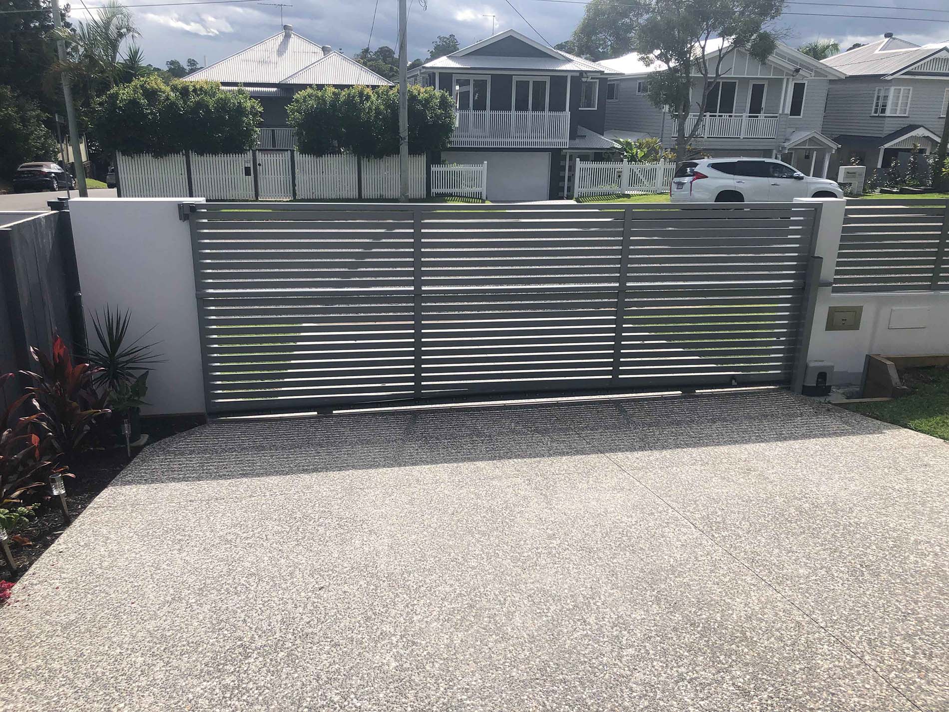
Planning a sliding gate installation
The more time you spend at this stage the less mistakes made and time wasted doing rework, so spend a bit of time getting this part right. Any sliding gate has only a few key parts that need consideration - the track, the gate, guide support post or pier, receiver post or pier.
The automation section has many more considerations but just for the moment let’s concentrate our planning on the basics as they remain constant whether the gate is automated or not.
The first thing we need is two definable points to determine our gate opening. You may have existing posts, brick or concrete piers. If not you will need to allow for the installation of posts or piers to act as a receiver on closing and guide support.
If you are installing new posts we would suggest 75mm - 100 mm square as a good size and if concreting into the ground a minimum of 600mm in concrete with legs attached.
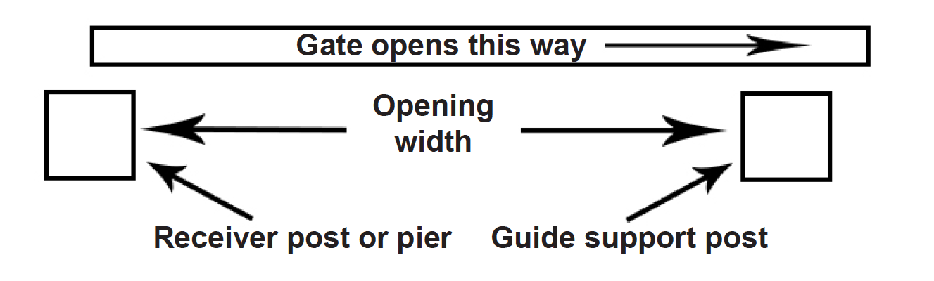
Once we have determined our two points we can start to look for and record some information -
The opening width between our two posts or piers.
From the opening width we add an extra 100mm to each end of the gate. This will give us our overall frame length.
Then allow a 300mm tail for the bottom of the gate frame which will allow the motor to sit well away from the driveway.
Once we have a total gate length (including any tails) we can check to ensure sufficient room to slide the gate open fully without impeding the opening.
Concreting in posts
Sounds simple enough I hear you say. Poorly installed posts account for 90% of all gate problems. If the post moves, the gate fails – it’s that simple!
Start with your post. As a good guide one third of your post should be in the ground. In other words if your gate post is 1800mm high, half that is 900mm, your total post length is now 2700mm. The 900mm in the ground is one third of the total post. A minimum of 600mm should be in the ground no matter what, so all gates under 1200mm high still put 600mm in the ground.
Fit a leg or two to your post. A post without any cross braces or legs to anchor the post in the concrete will simply slide out of the concrete when dry or worse still may sink down if no concrete has been put underneath. Put at least one decent cross brace about 300mm up your post and about 150mm wide or place a tile under the post.
Dig your hole deep, not round. A common mistake is to dig a one metre by one metre hole but only 400mm deep. Do not. 400mm x 400mm x 1000mm deep is much better and takes less than half the concrete.
Gate construction
The easiest place to start is the bottom rail of the gate. The bottom rail is generally 100 x 50mm. This will give you more overall strength and added room if installing your motors gear rack at the bottom. Sides and top are typically 50 x 50mm. Gate fill is obviously a personal choice.
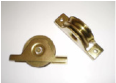
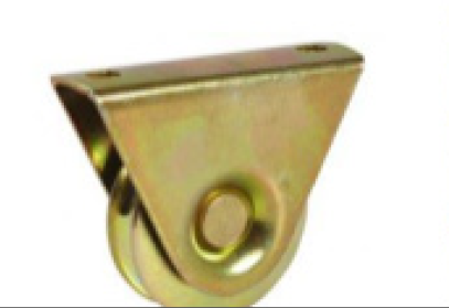
A pair of wheels will need to be installed at 25% in from each end of the gate. There are 2 types of wheels available. ‘Trapeze’ (high profile) is a wheel that bolts directly under your gate while ‘Support’ wheels need to be inserted into your bottom spin rail of the gate so only a portion of the wheel is exposed. BMGi supply ‘Support’ wheels.
How to fit wheels to your sliding gate
To attach the wheels to the gate you must decide on a suitable position as mentioned above. The most common is about 1mtr from each end, however, if your concrete is uneven then you may need to go further in so as the centre of the gate does not hit the gate track.
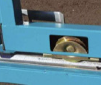
Option 1: Support Wheel
Depending on the position of the cradle determines the width of the cut hole in the gate. Only cut a rectangle hole big enough to fit the portion of the wheel required. This is done using a simple hand grinder with a cut off blade once you have marked the hole with a marker or tape. Place the gate at 45 degrees on 2 x trestles so you can safely cut the holes. Be sure to protect the gate from damage with soft mats or do it on grass. When cutting the hole you will not need to cut right up to the corners with alloy but near enough...use a hammer and punch to tap the excess rectangle into the gate and remove it once free from the corners. Fit the wheel into the hole and check for free running. Use standard fasteners to secure the wheel to the gate.
Option 2: Trapeze Wheel (BMG does not stock this type of wheel)
Sliding gate track
Perhaps the two most basic fundamentals of planning a track for a sliding gate are straight and consistent. I say consistent because it is not necessary for a track to be level left to right, but it must be consistent. In other words, if your driveway has a consistent drop from one side to the other of say 200mm, then the run off portion of your track must also fall 200mm so that the entire track, which is twice the length of your gate opening falls a consistent 400mm. No rises and falls but a smooth, consistent drop.
Straight is pretty much common sense. The centre of your track should generally be about 100mm from your guiding post or pier for a 50mm thick gate. This dimension will vary dependent on your gate thickness roller configuration.
What type of gate track
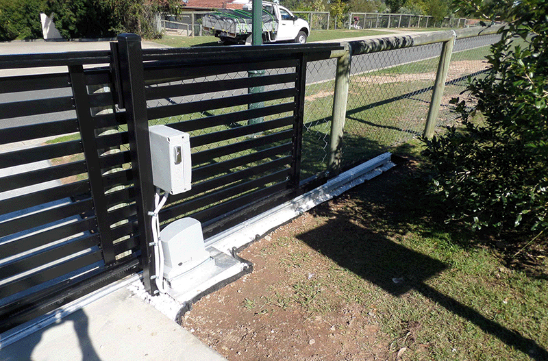
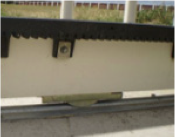
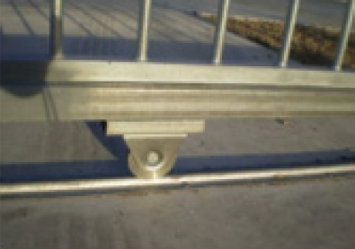
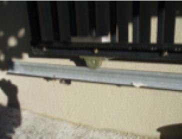
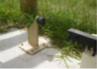
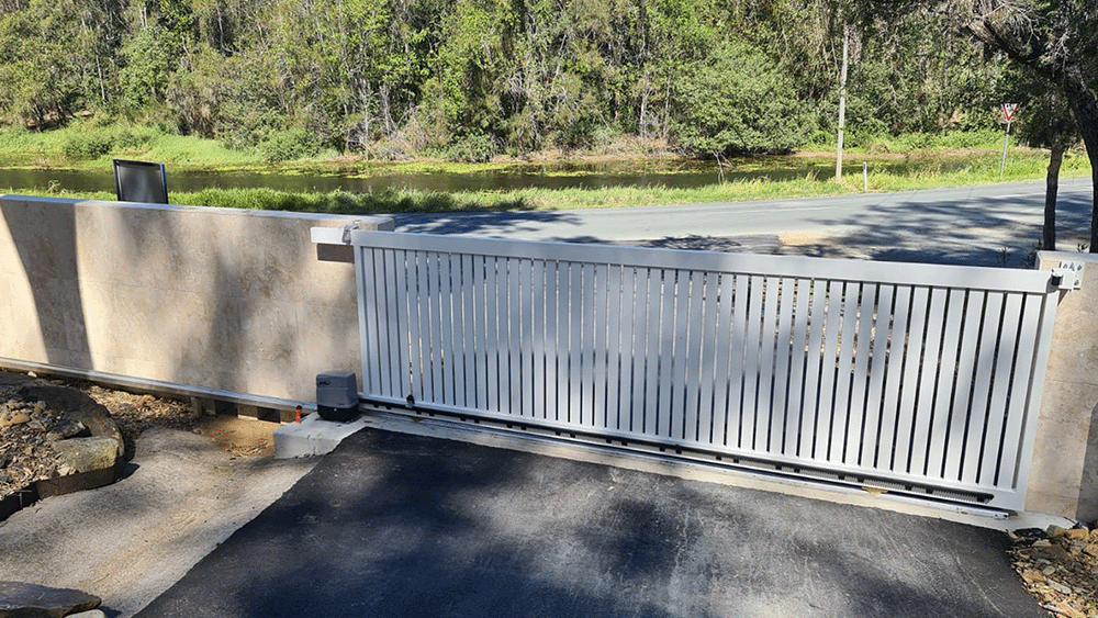
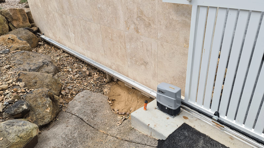
Bolt Down Track is by far the most preferred method. This type of track assumes you have a surface suitable to bolt down to. Usually an existing concrete driveway or in some rare cases well secured and level brick paving will suffice if traffic flow is not heavy or constant. Most professional installers prefer to lay a full concrete plinth and then bolt down the track. Their argument is that using bolt down track gives them flexibility and allows a section to be replaced if damaged. When bolted down to an existing driveway it is not unusual to see the back edge of the track or “run off” section with brackets or legs at 500mm intervals either bolted to an existing wall or concreted at footing points (see photo below). This is acceptable in most cases as there will be no traffic over this section and will carry the gate only.
Concrete In Track a full concrete plinth - typically 250mm x 250mm x twice gate width long with concrete in track embedded. Reinforcement can be added if re-quired. The concrete in track is designed to be simply pushed into the concrete and we find it easier to pour the plinth, get your basic levels, push the track in and finish off, many however prefer setting the track up with supports before the pour, pour-ing around the track and simply finishing off later. If ordering concrete you need to know how much and what type. The two mixes we use most commonly are known as 20/20/80 which is a standard footing mix and 25/10/80 which tends to be a little easier to finish but more costly. To calculate the amount multiplies your plinth width by its depth by its length in metres to give you a cubic capacity. Example - My plinth is .25 x .25 x 12 metres = .75 cubic metres. Now your local concrete company may have minimum quantities like 1 cubic metre but at least you know you have enough.
Full concrete plinth allowing for driveway completion this is the most common type of track and is simply a concrete plinth poured to give allowance for driveway finishing, be it a brick paving header course or Asphalt etc. A few different levels can be used to achieve different finished results.
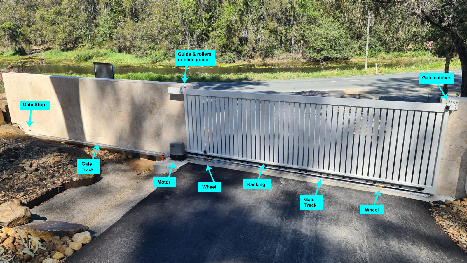
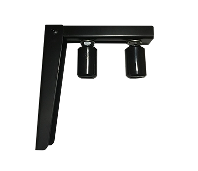
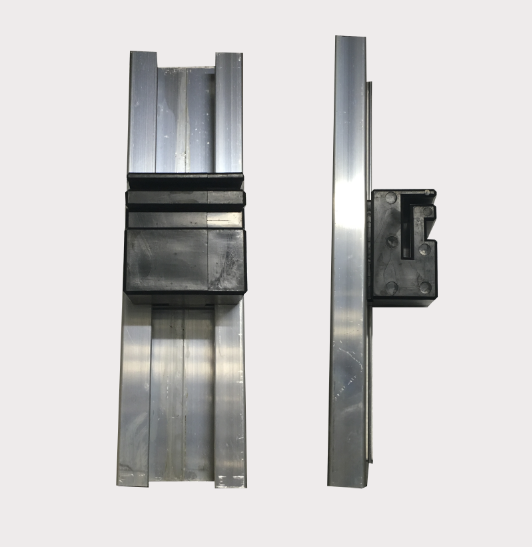
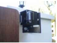
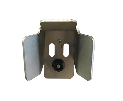
Guide bracket with rollers or slide and guide block
Once the wheel track is positioned you can install the guide bracket above the gate. Positioned on the post behind the motor this bracket is to prevent the gate from falling over and guide it left and right.
If you have a decent fall over the driveway or you have pailings attached to the gate frame you may need to consider using a slide & guide block. When using this method you do need to place a piece of aluminium angel along the back of your gate frame to allow the block to sit in and slide along. This will require an extra post at the motor end to attach your slide & guide block too.
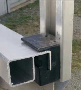
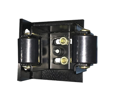
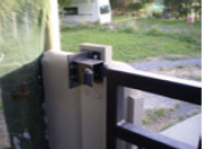
Gate catcher
Positioned on the post at the closed gate end the gate catcher guides the gate to the closed position and prevents the gate from being lifted off the track. There are 2 types of gate catchers. The standard butt catcher is used for positions that the gate will butt up to the post and the side mountable catcher for gates that will pass the end post which are positioned inline with the centre post. The BMGi's Side Catcher is fitted with 2 rollers and can be adjusted up and down as well as sideways giving a higher level of installation options.
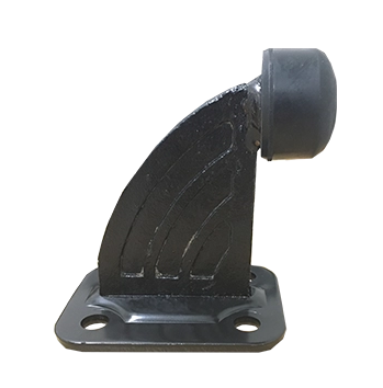
Gate stopper
Positioned on the ground to the rear of the fully open gate to stop the gate running off the wheel track or guide bracket. This is an important safety device that should be installed to prevent the gate falling on children or animals.
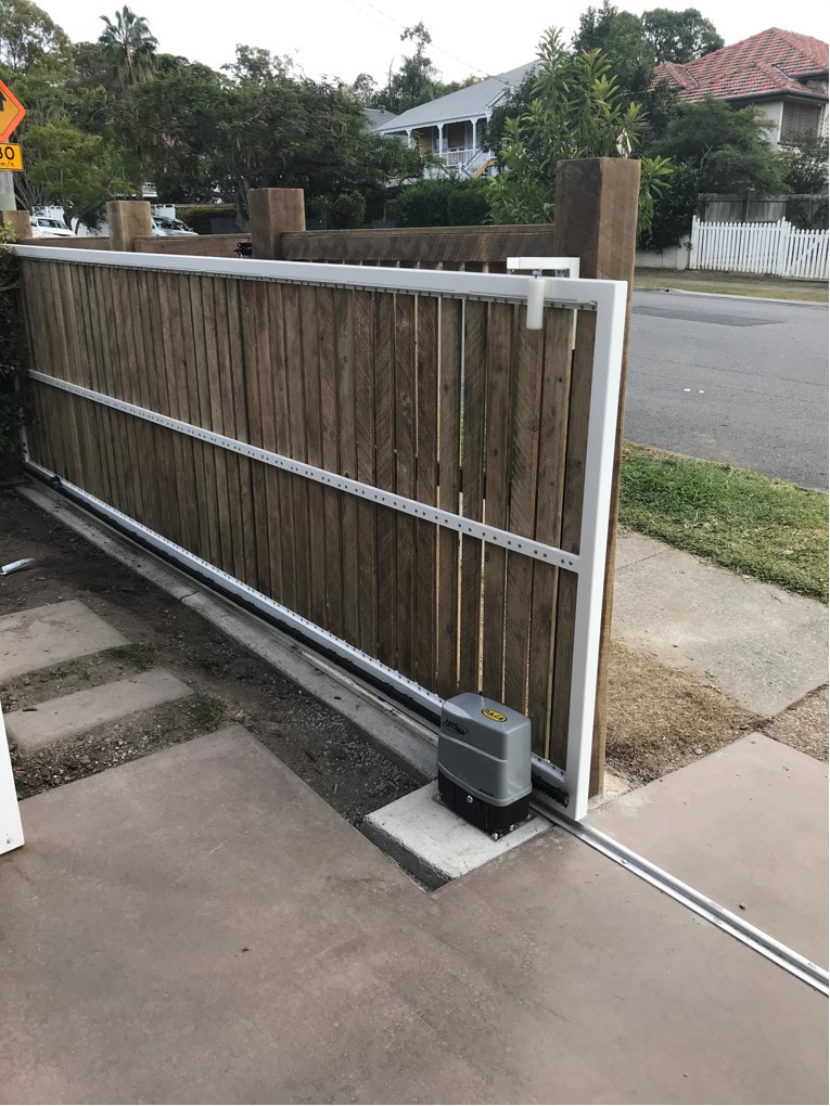
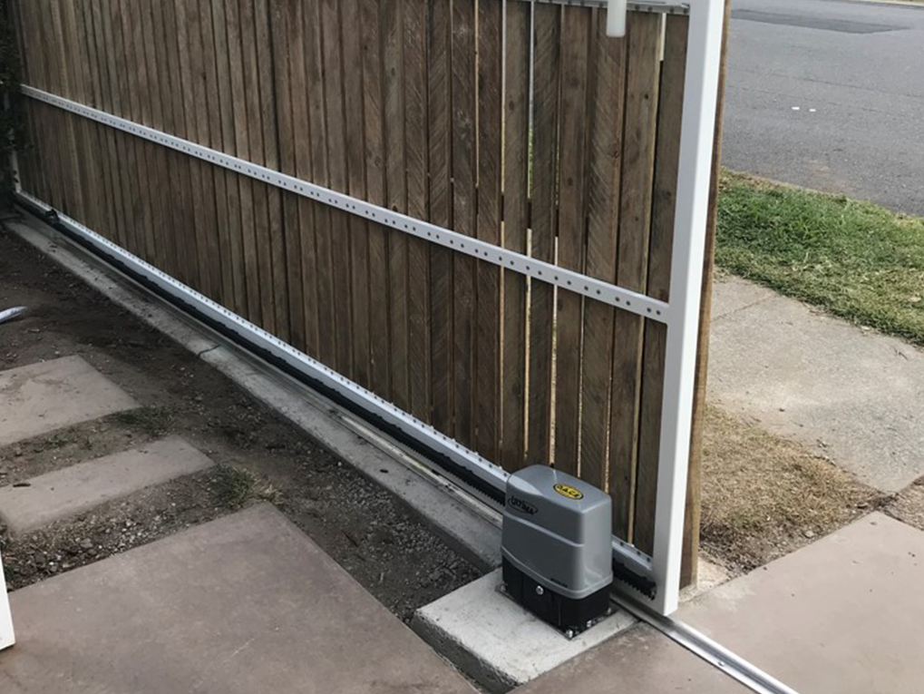
Mounting your gate motor and gear rack
The most common method of motor mounting is to bolt down to a pre prepared concrete pad although most motors have a base plate available that can be installed in concrete beforehand with your track work making the bolt down procedure even simpler. Use a length of rack to position your motor in relation to the gate and take into account limit switch positioning.
Once you have bolted the motor down securely use your manual override to put the gate into manual mode. Start at one end and use tek screws (supplied) to fasten your first length of rack centred over the pinion or sprocket. The rack should not sit directly on the pinion but have a 2-3mm gap between the pinion and the rack. Use a 1-1.2mm spacing washer under the 4 corners of the motor base plate while installing the gear rack, then remove these to do the final setup. Slide the gate back and forth to ensure the first length is level. You can now slide the gate along until the pinion is about 80mm from the end of the first length of rack. Attach the next length of rack into the interlocking point of the first length of rack and position the other end of the rack on the pinion. You should now be able to fasten this length of rack at two points and move along to the next and subsequent lengths. You may need to cut the last length to suit. When all lengths are fitted, remove the spacing washers and re tight-en the motor to the ground. Check the operation of the rack before inserting all fasteners.
Ready to power and program
At this point I assume you have had your power professionally connected and all other wiring has been completed. My simple suggestion here is that you leave most extras like photo cell beams and keypads not connected, until after you finish programming and have your gate running smoothly. Having bells and whistles connected will only complicate matters if things don’t go exactly as expected. By having the bare basics makes fault finding much easier.