Troubleshoot this device
Master Code = 999999 is the default factory master code
PIN = any four digits between 0000 & 9999 with the exception of 1234 which is reserved
User ID Number = any number between 1 & 2000
Important: if entering a number of different Pin Numbers into the keypad, it’s advisable to record the ‘User ID Number’ that matches to your ‘Pin Number’. If you need to delete a Pin Number in the furture you will need the User ID Number to remove it. If you fail to record these numbers then you will need to wipe all keypad numbers and start again.
We do recommend that you change the factory master code (999999) to a secure code which you must make note of. Failing to make note of your new master code will prevent you from being able to add or delete pin codes in the future. You would then be required to perform the 'reset'.

Please note, with all the instructions below we have used the factory Master Code of 999999.
If you change this master code then you will need to use your new one instead.
How to enter a new pin code
- Press *
- Master Code (factory 999999) #
- 1
- User ID number (pick from 1 up to 2000) #
- PIN (0000 up to 9999) # * *
How to enter a new pin code - EXAMPLE
- Press *
- 999999 #
- 1
- 100#
- 2468 # * * (2468 is now your new pin)
How to delete a pin code or swipe card/tag
- Press *
- Master Code (factory 999999) #
- 2
- User ID number # * *
Note: if you have forgotten your User ID Number, then you will need to delete everything stored in the keypad
Delete all keypad pin codes
- Press *
- Master Code (factory 999999) #
- 2
- 0000 # *
Adding swipe card or tag
- Press *
- Master Code (factory 999999) #
- 1
- User ID number (pick from 1 up to 2000) #
- Tap card or tag # *
If adding multiple cards/tags, each one should have their own 'User ID' for ease of deleting if required
Setting the relay close time
- Press *
- Master Code (factory 999999) #
- 4
- Select 1 sec # * *
Use this setting for double gates to both open.
How to change your master code
Your master code only requires to be changed if you require extra security on your keypad. You will need to take note of your master code as this will be used to add or delete pin codes in the future.
- Press *
- Master Code (999999) #
- 0
- New Code # New Code #
- New code can ber 6 to 8 digits
Reset to Factory Default
- Disconnect power from the unit
- Power the unit up, then press the # key
- On hearing ‘didi’ release the # key, system is now back to factory settings
How to enter in a new pin code on your Keypad
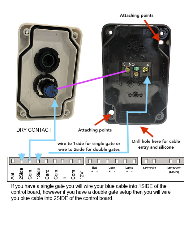
Wiring Diagrams
-
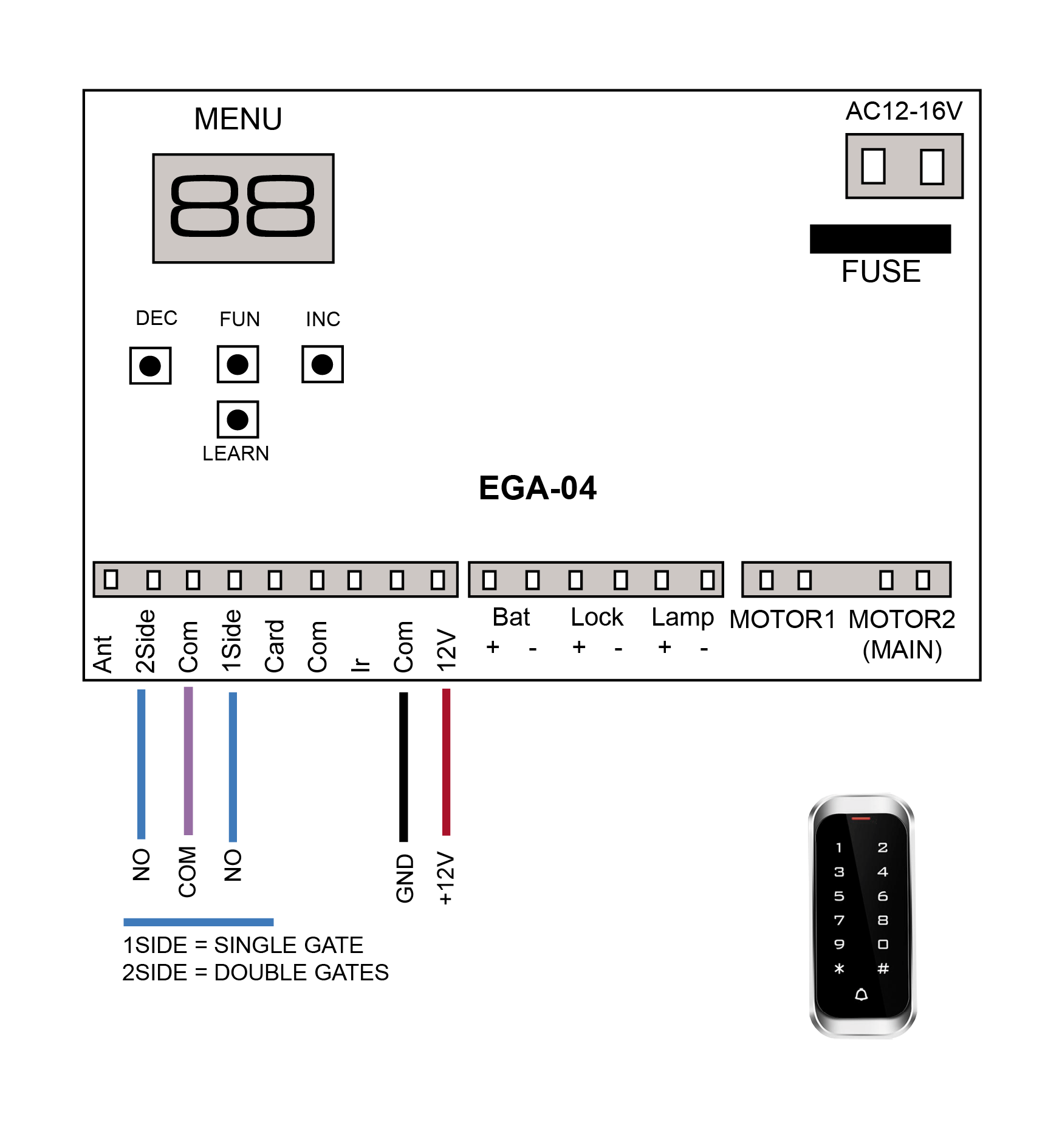
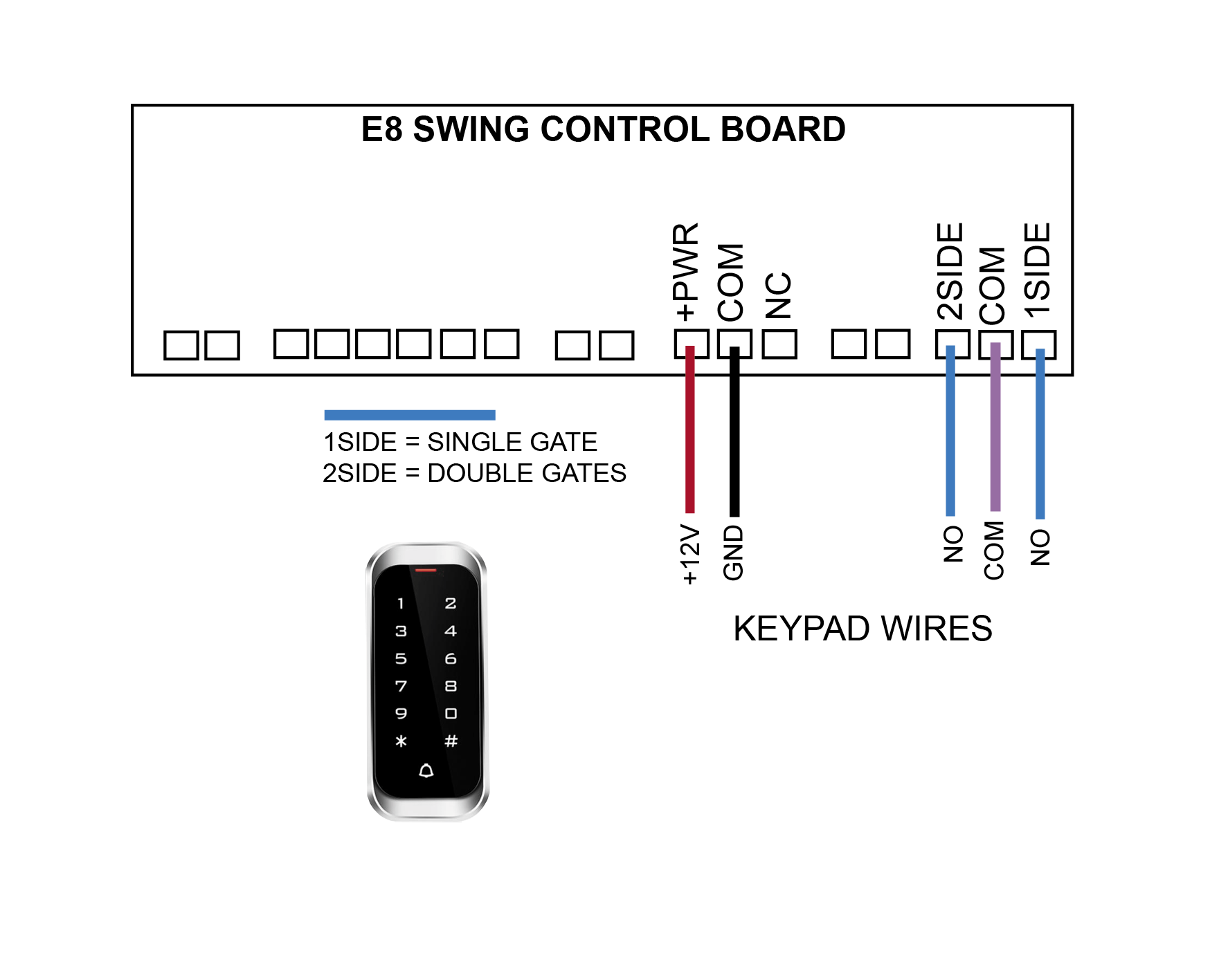
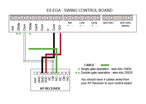
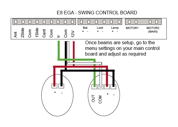
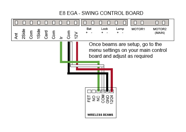
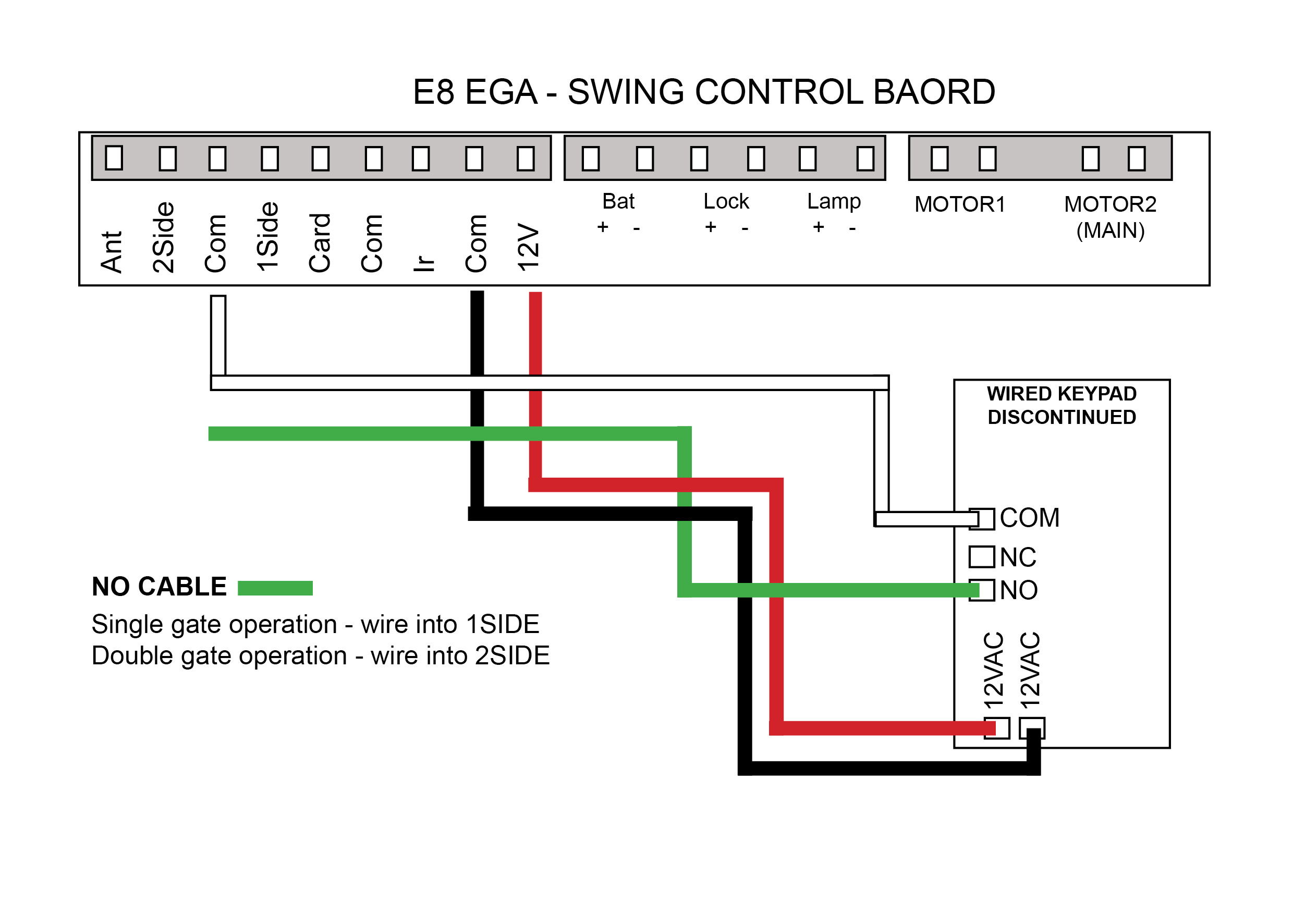
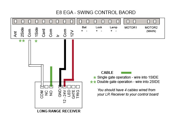
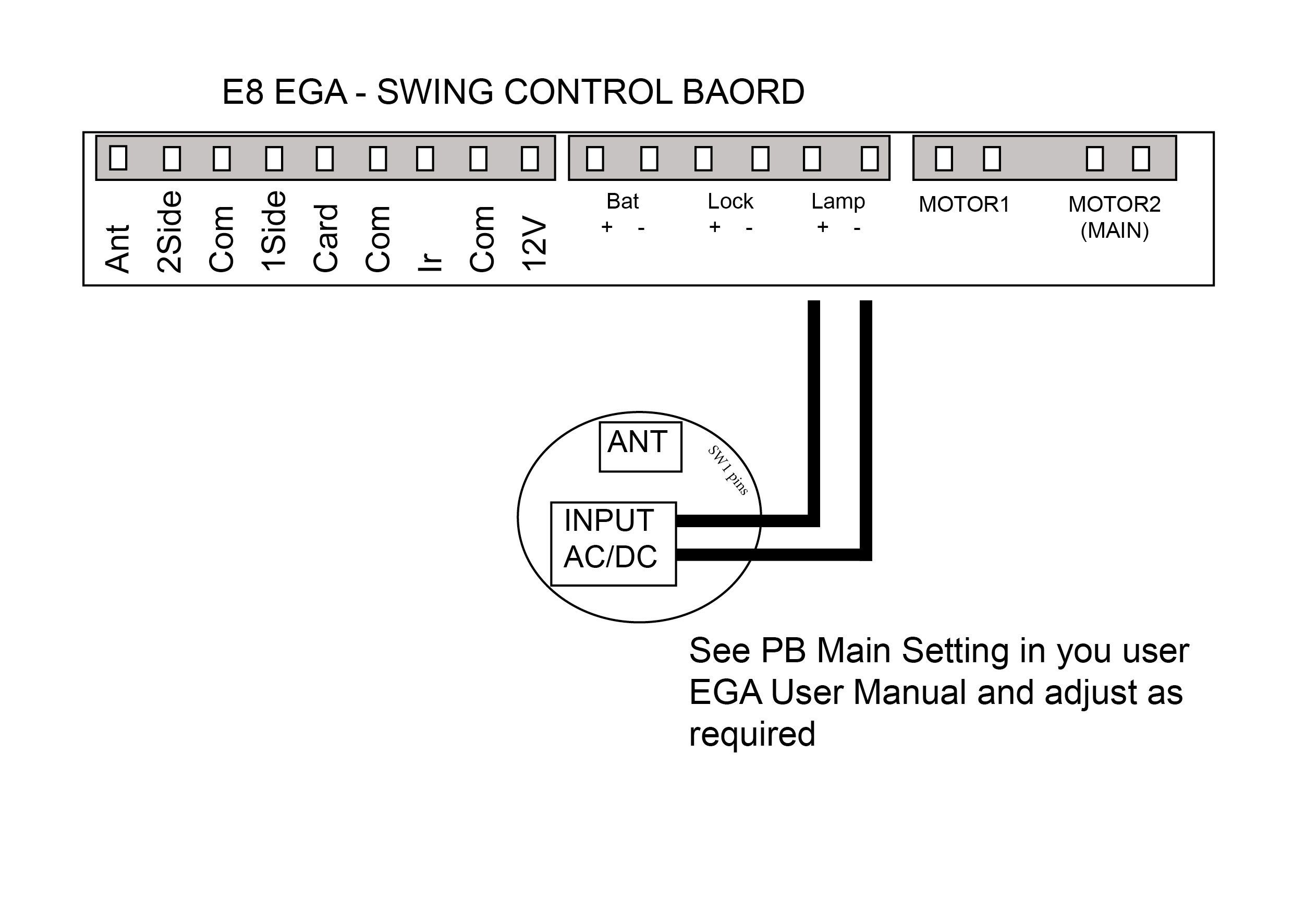
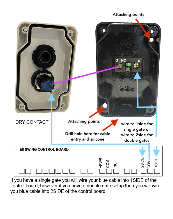
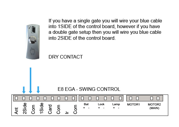
E8 - EGA Swing
Control Board
-

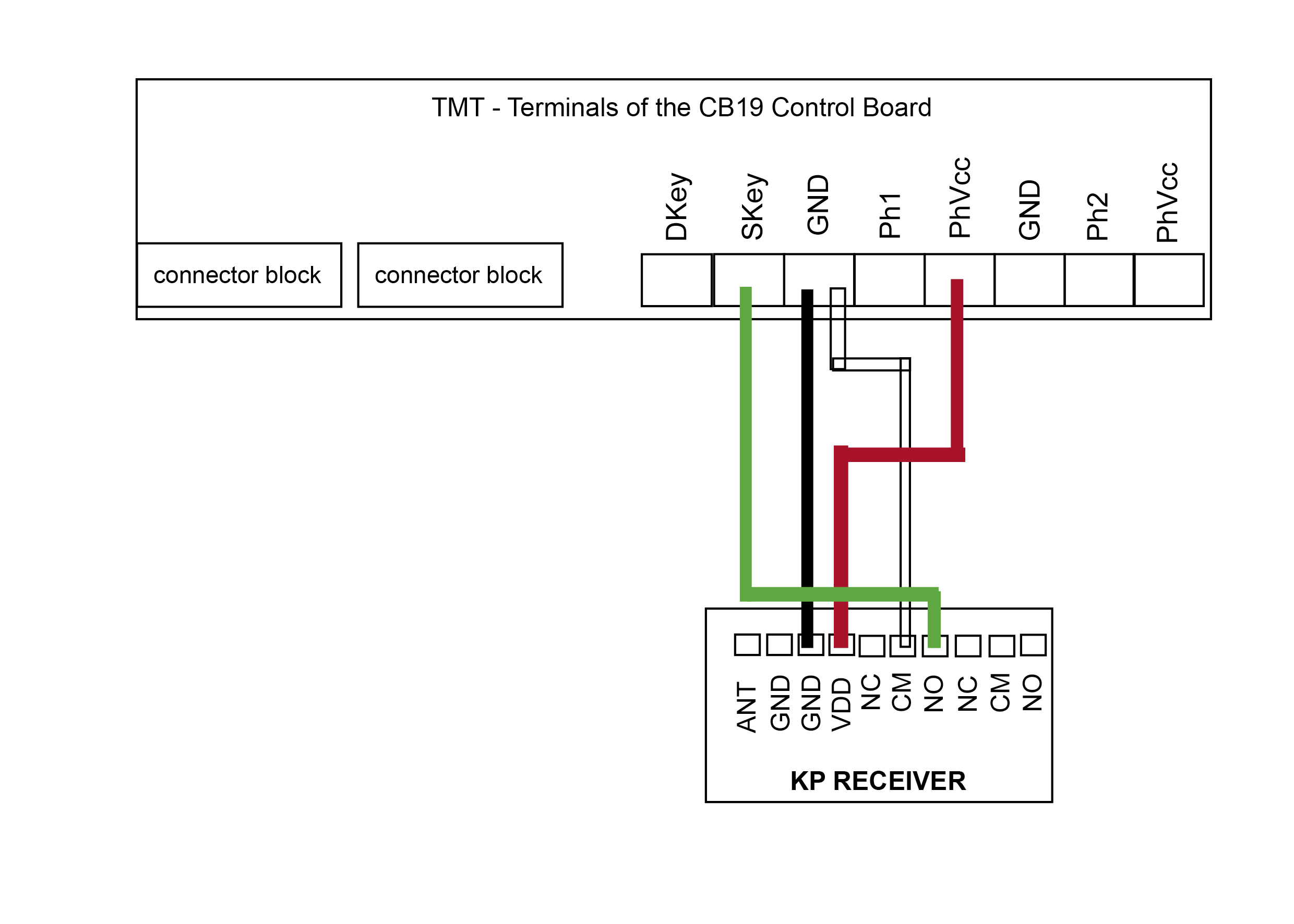
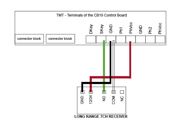
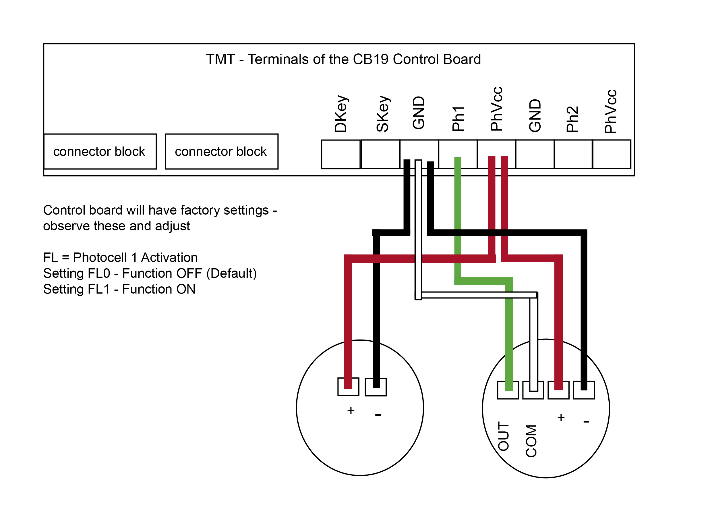
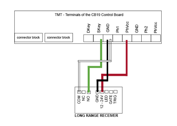
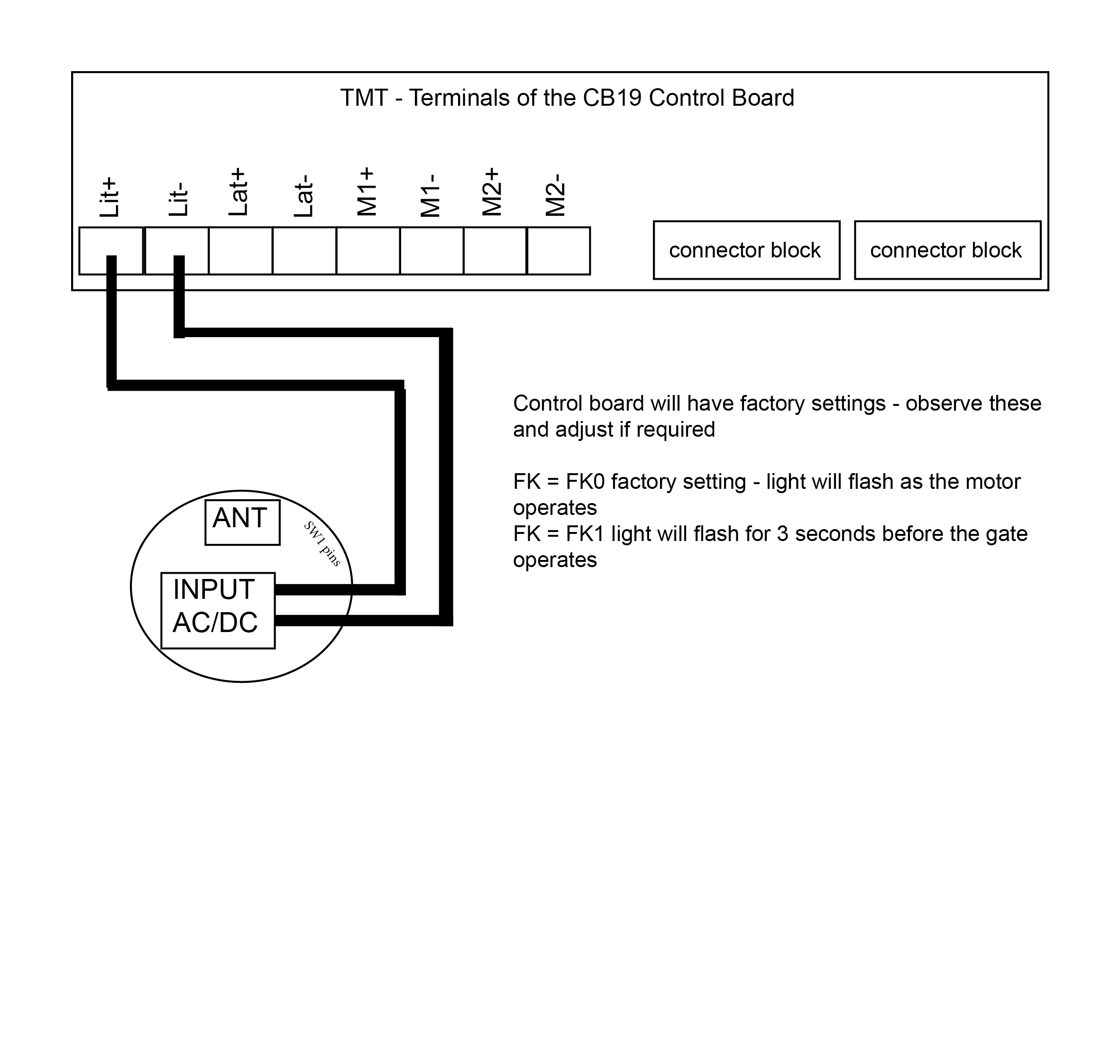
TMT 400LLS - Swing
Control Board
-
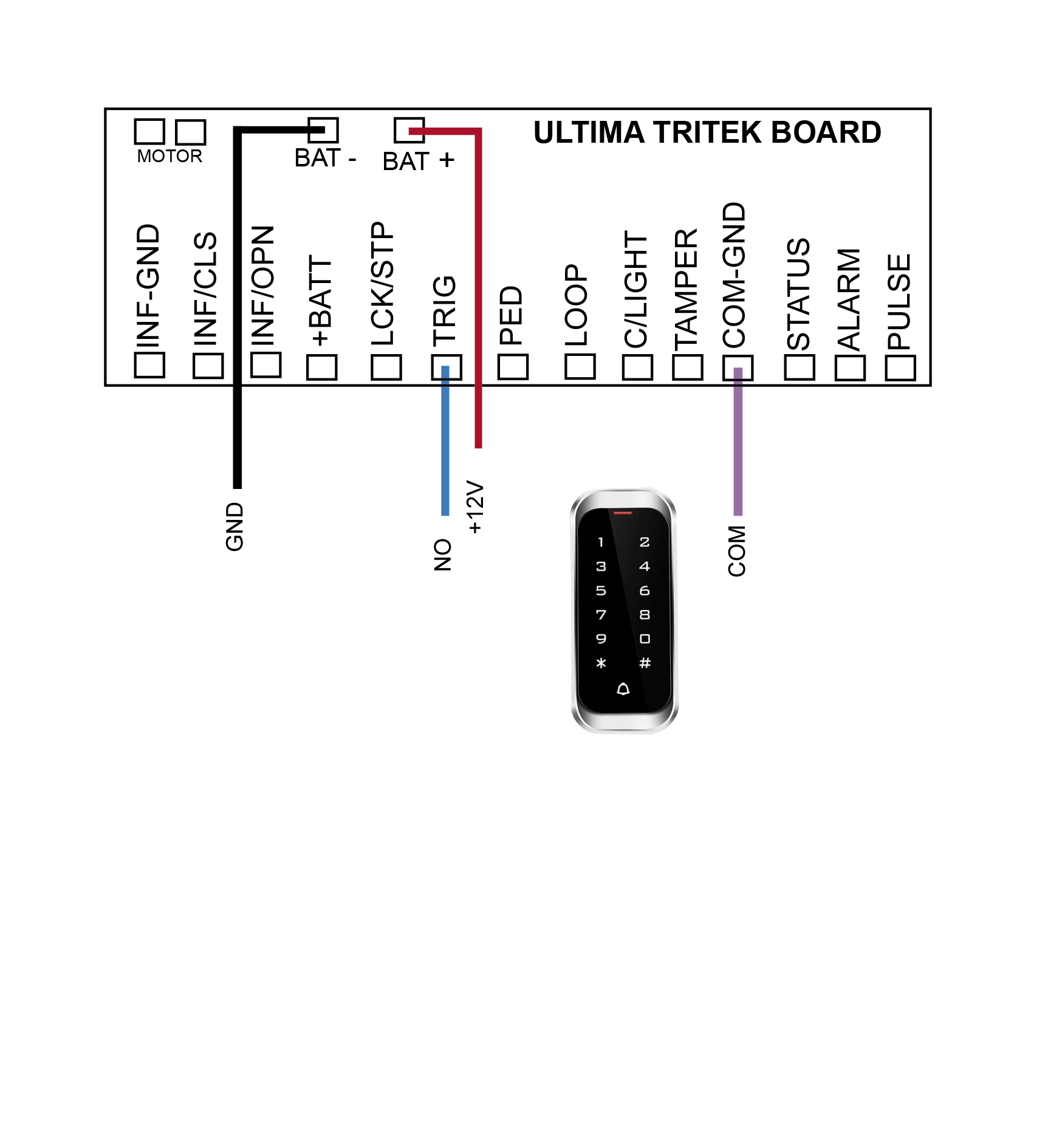
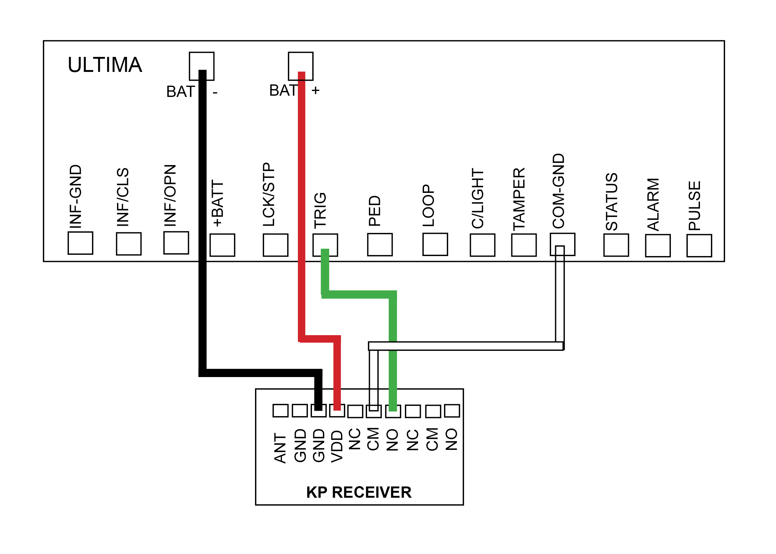
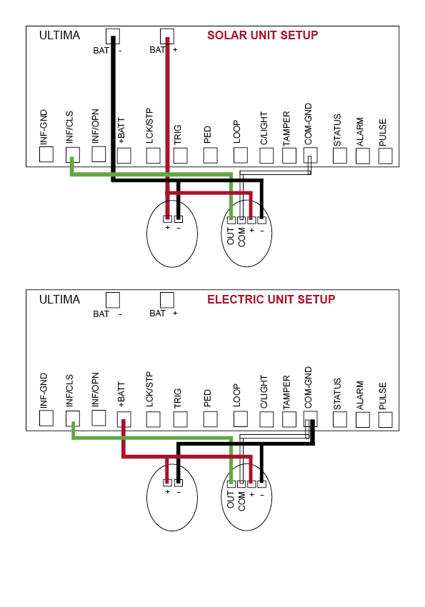
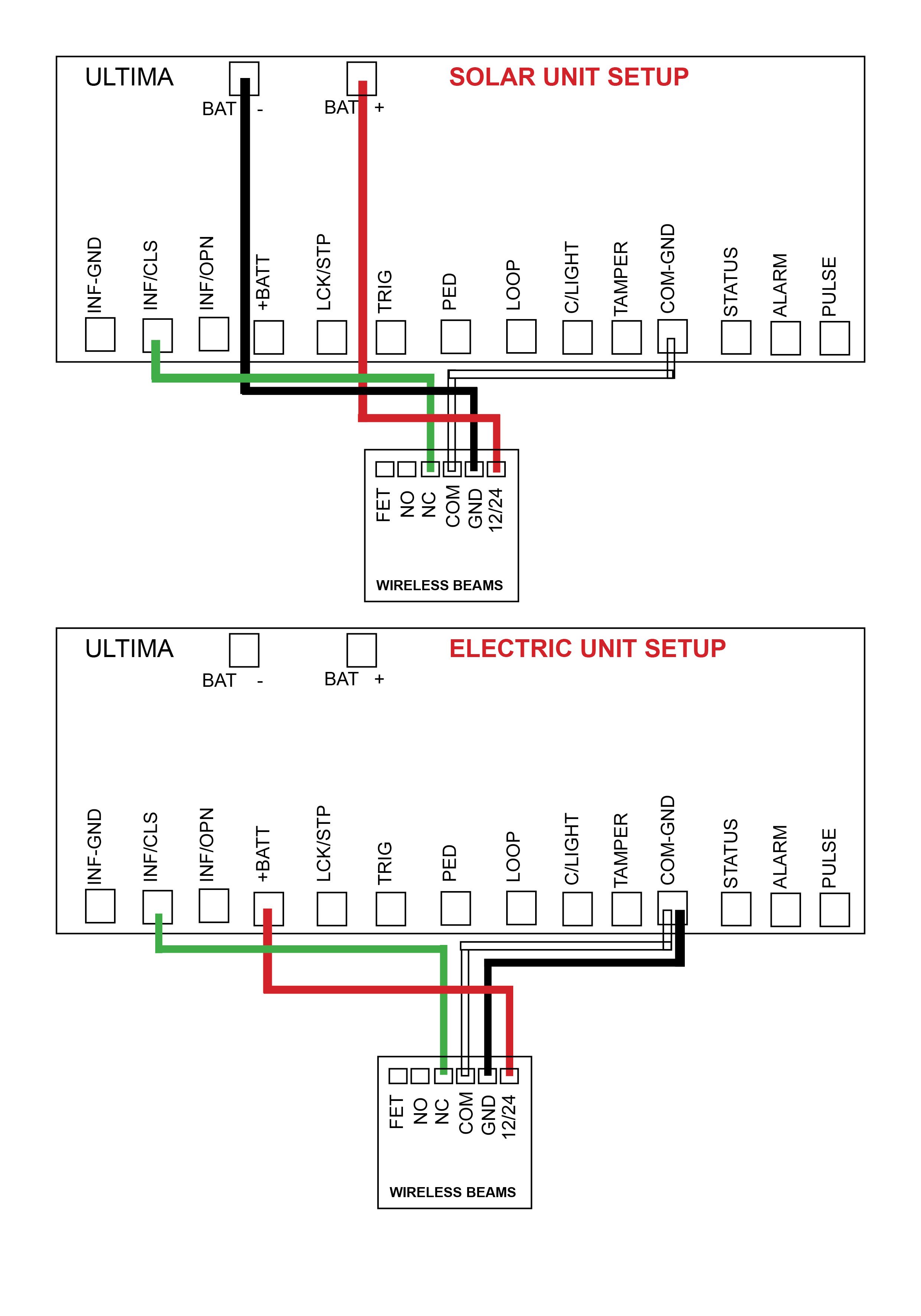
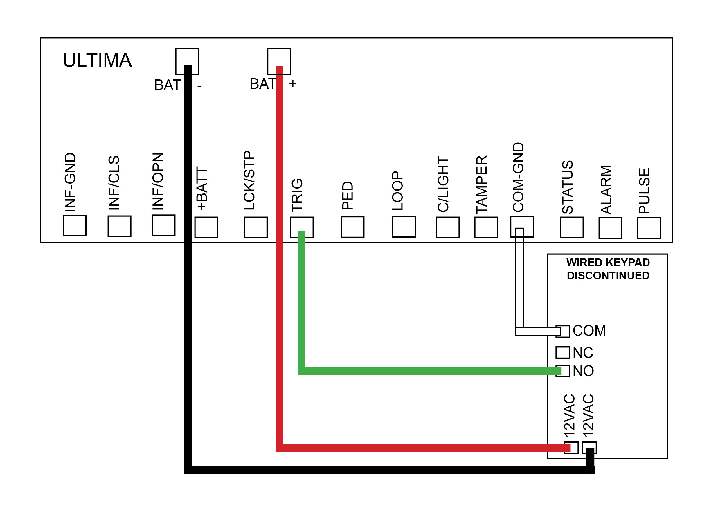
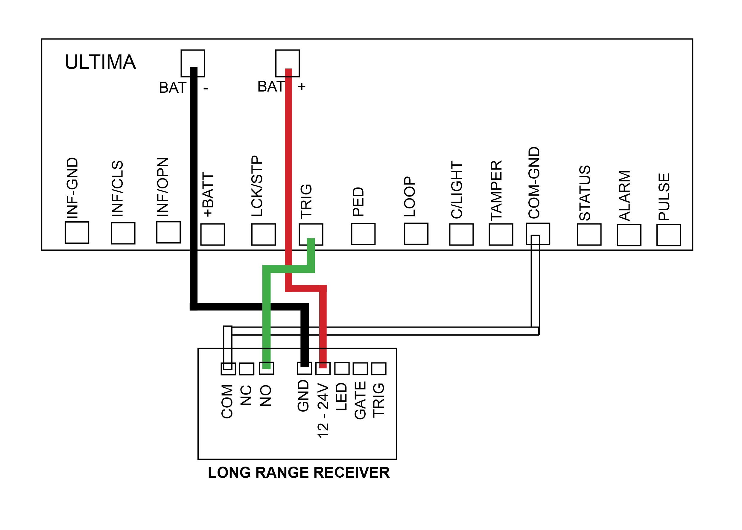
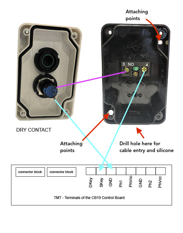
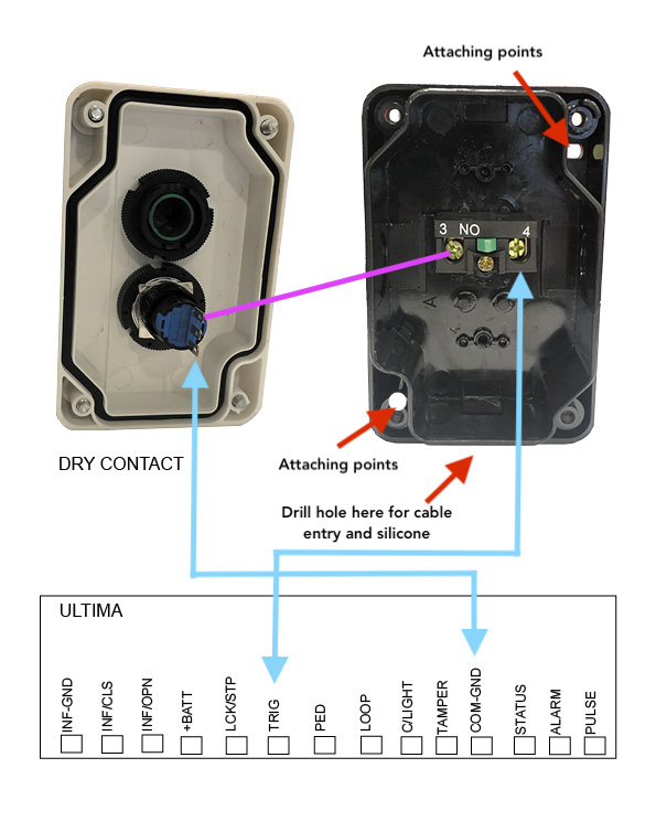
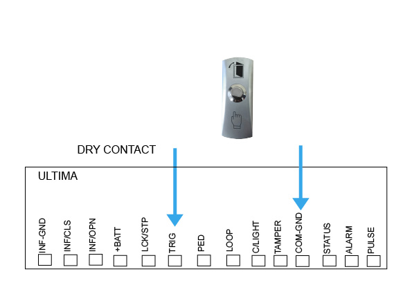
DACE Ultima
Control Board
-
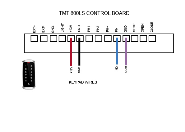
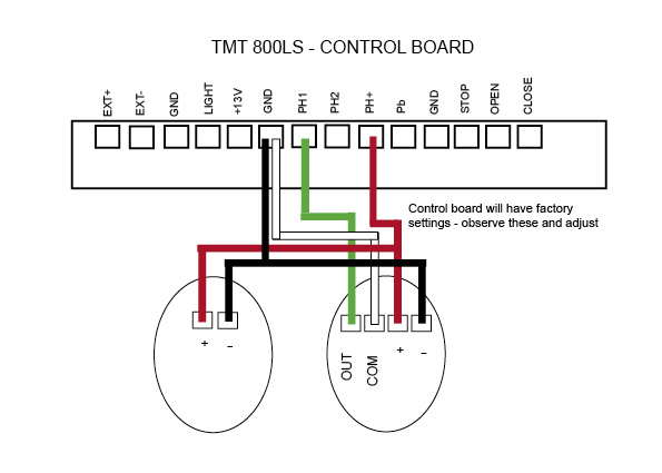
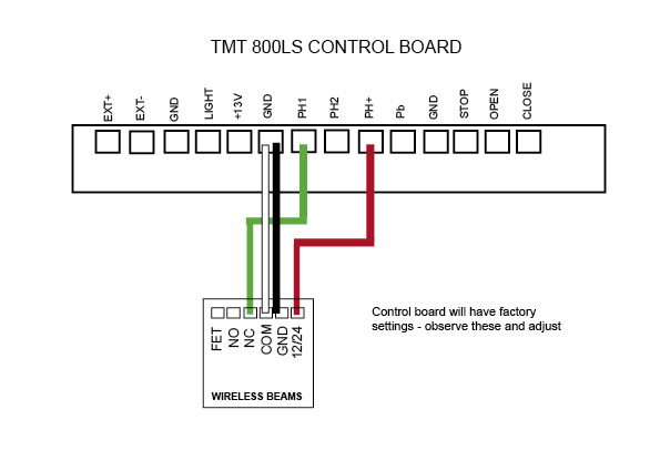
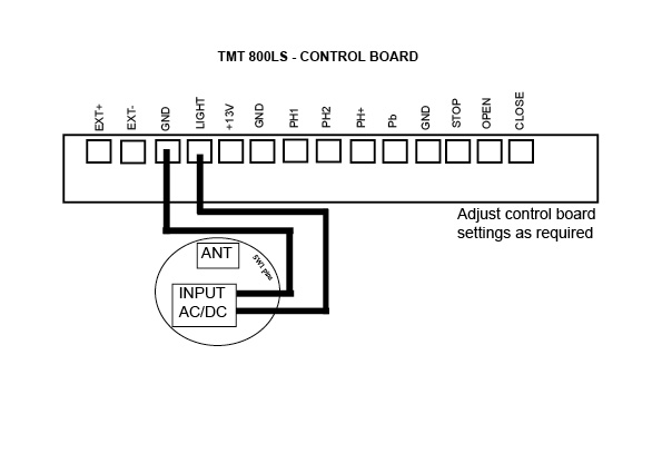
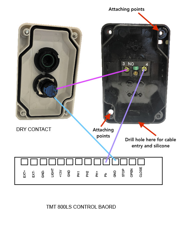
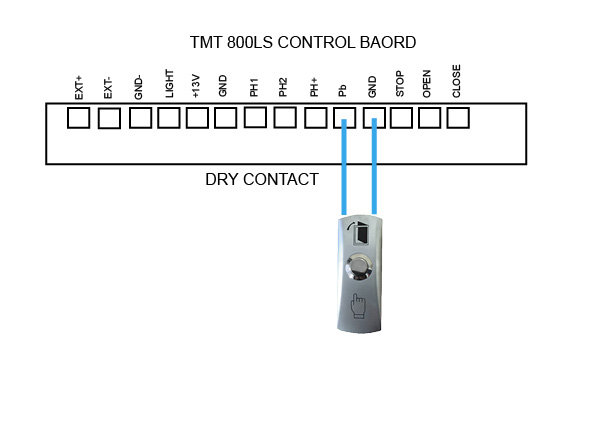
TMT 800LS
Control Board
-

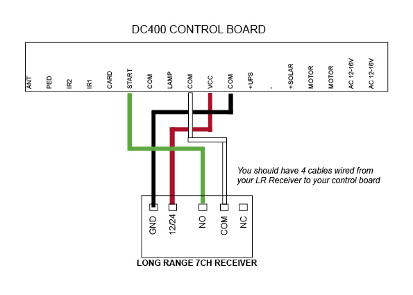
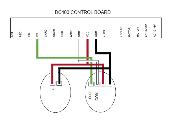
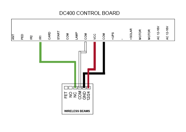
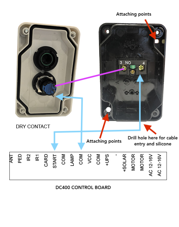
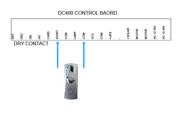
DC400
Control Board
-
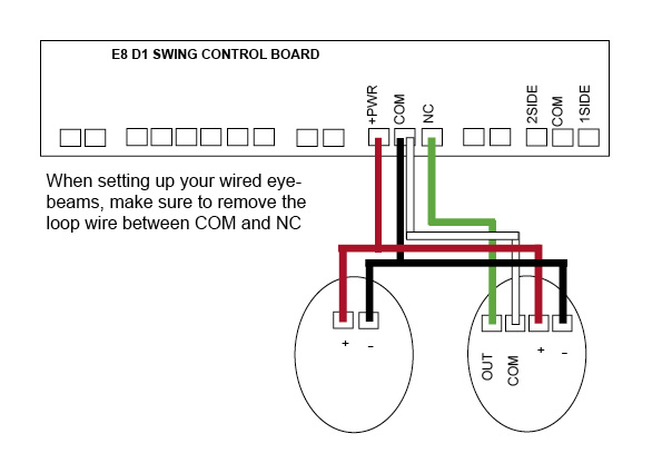
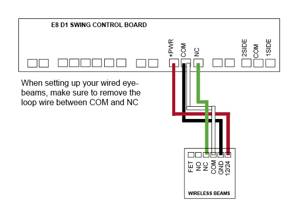
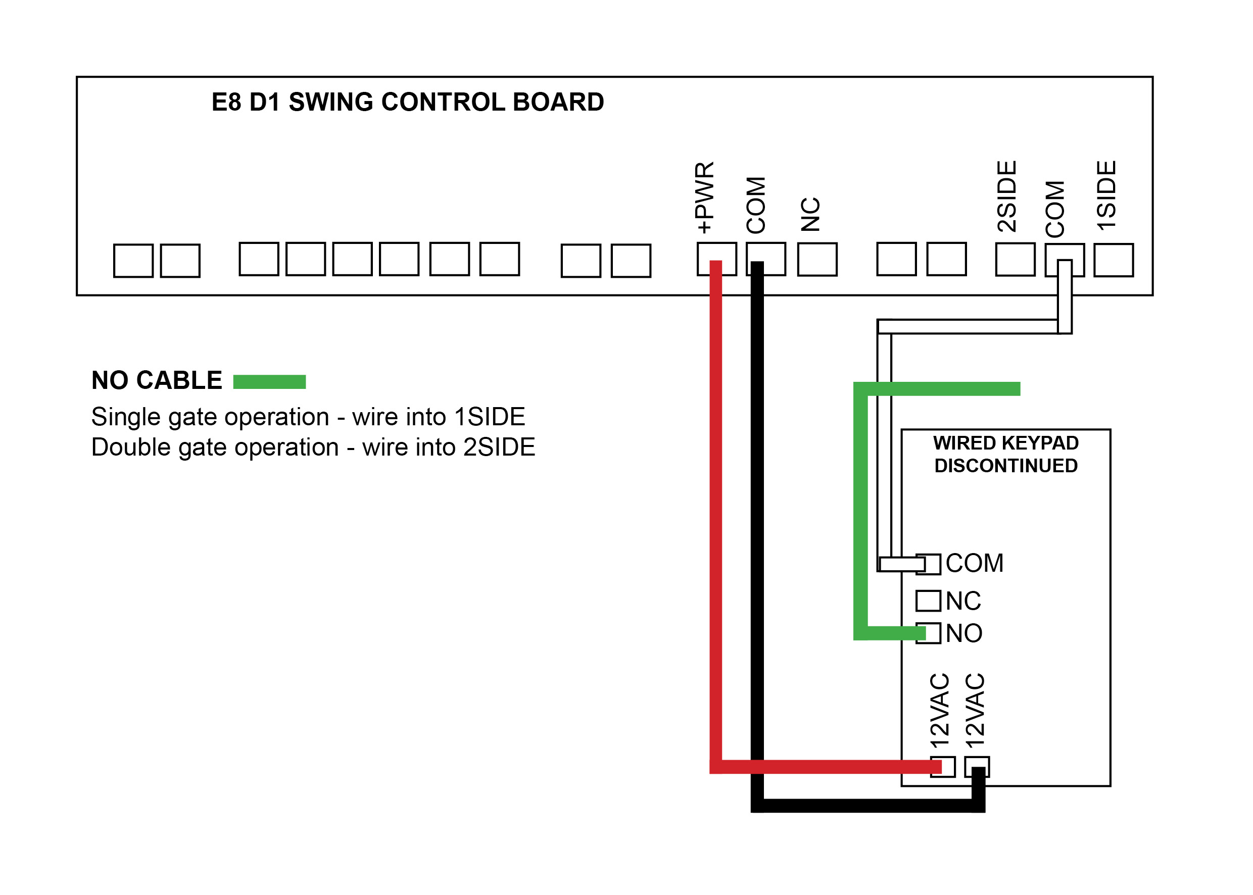
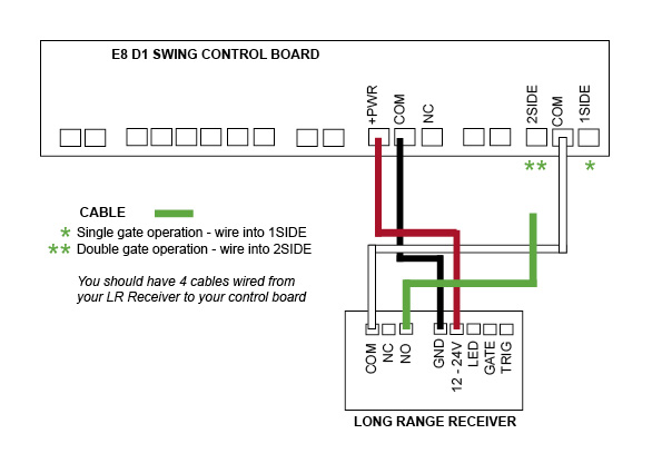
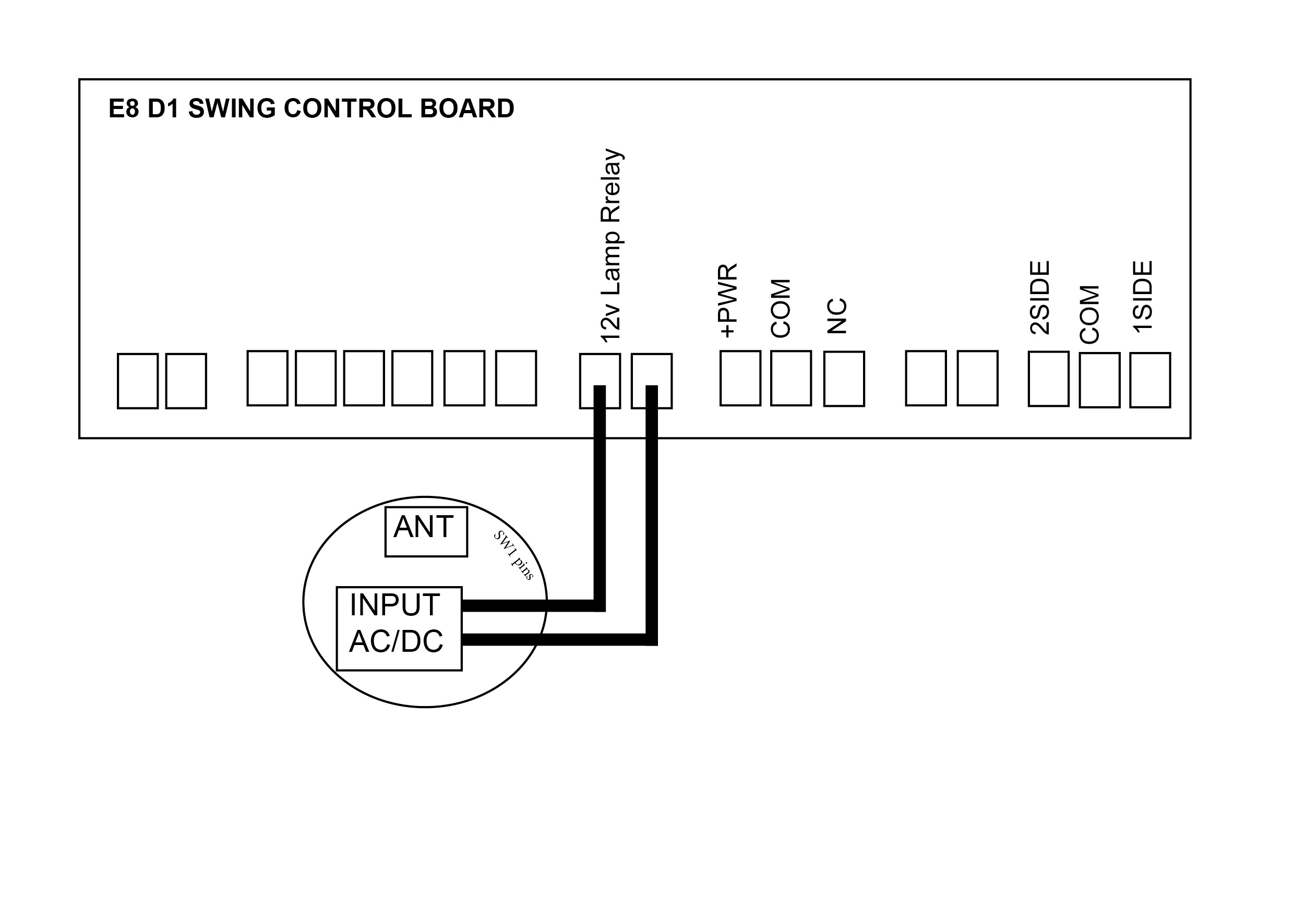
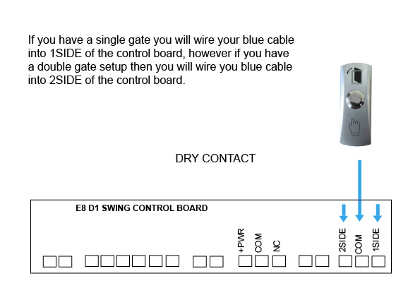
E8 - D1 Swing
(discontinued)
Control Board
-

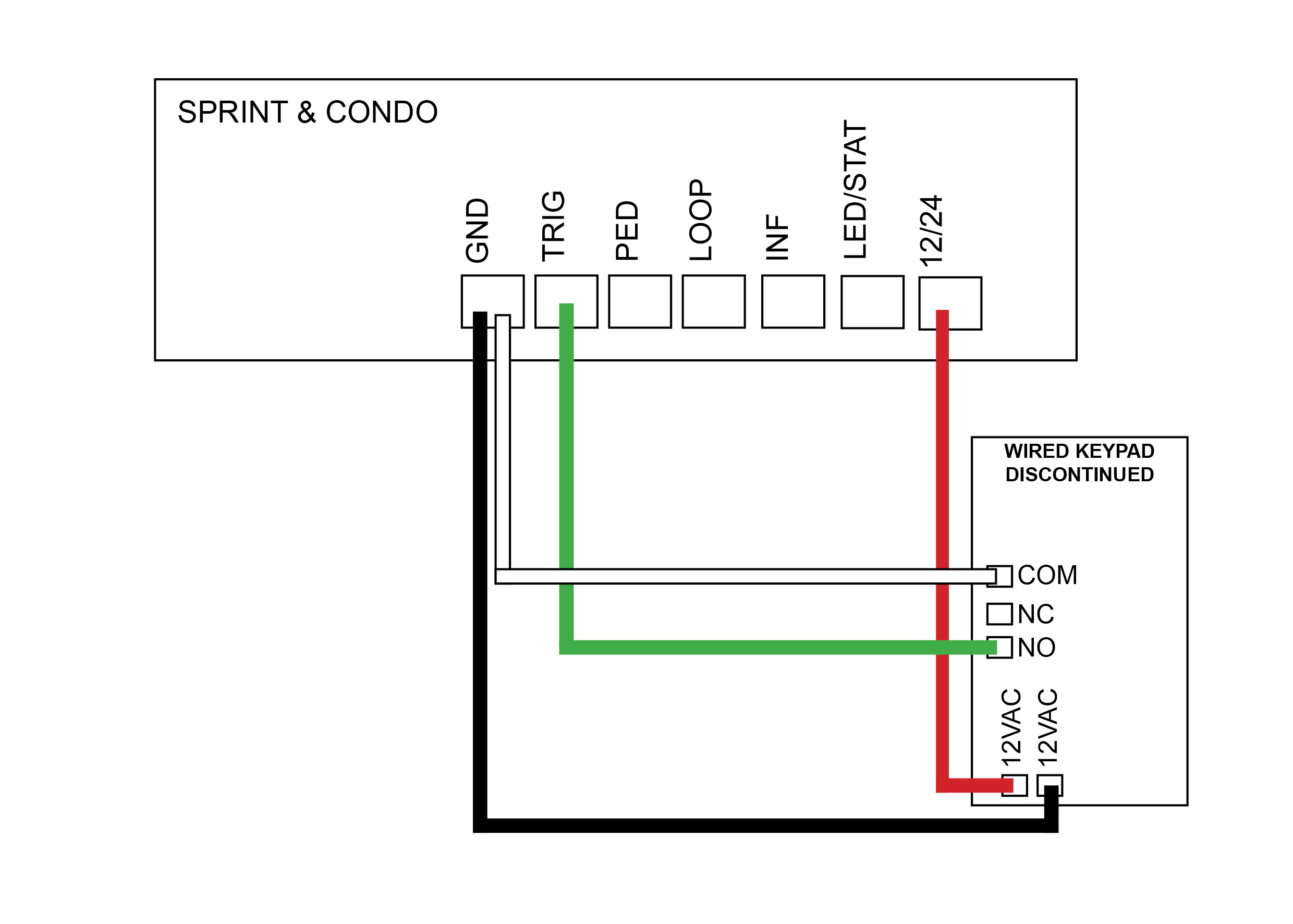
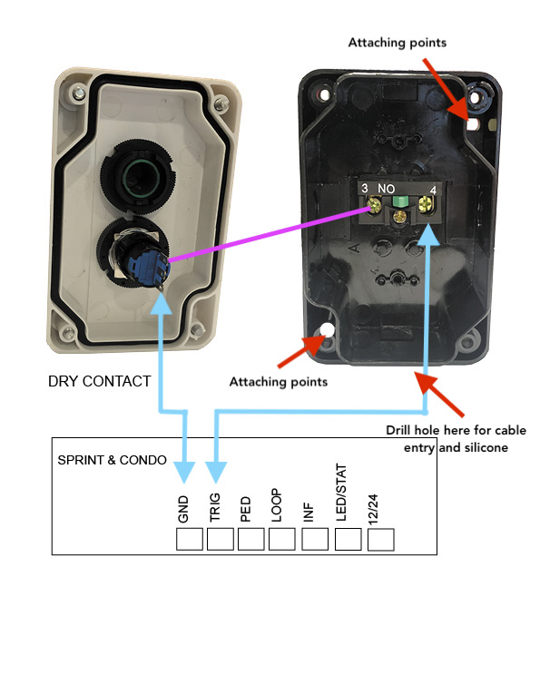
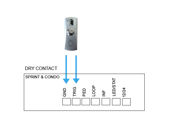
DACE Sprint/Condo
(discontinued)
Control Board
-
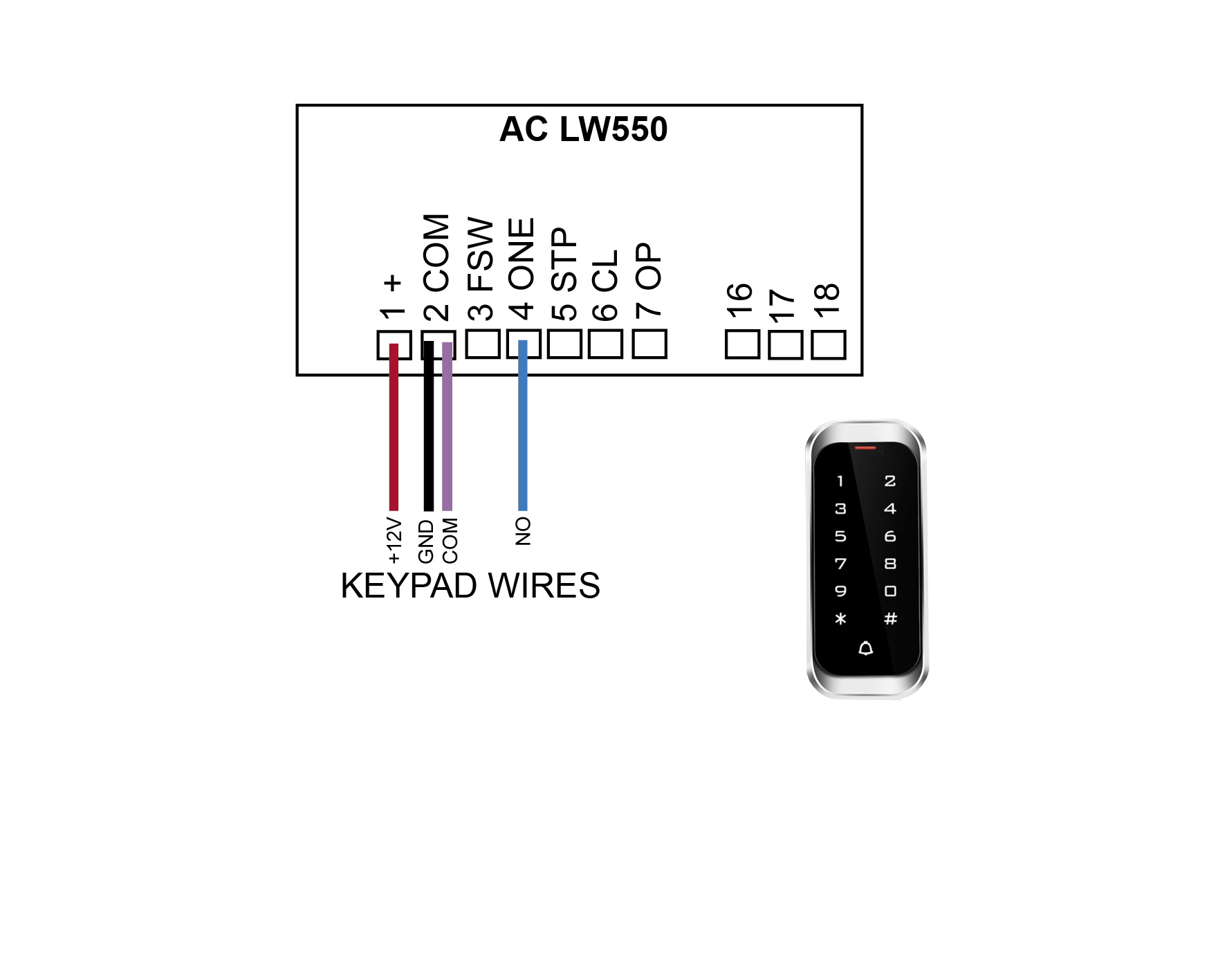
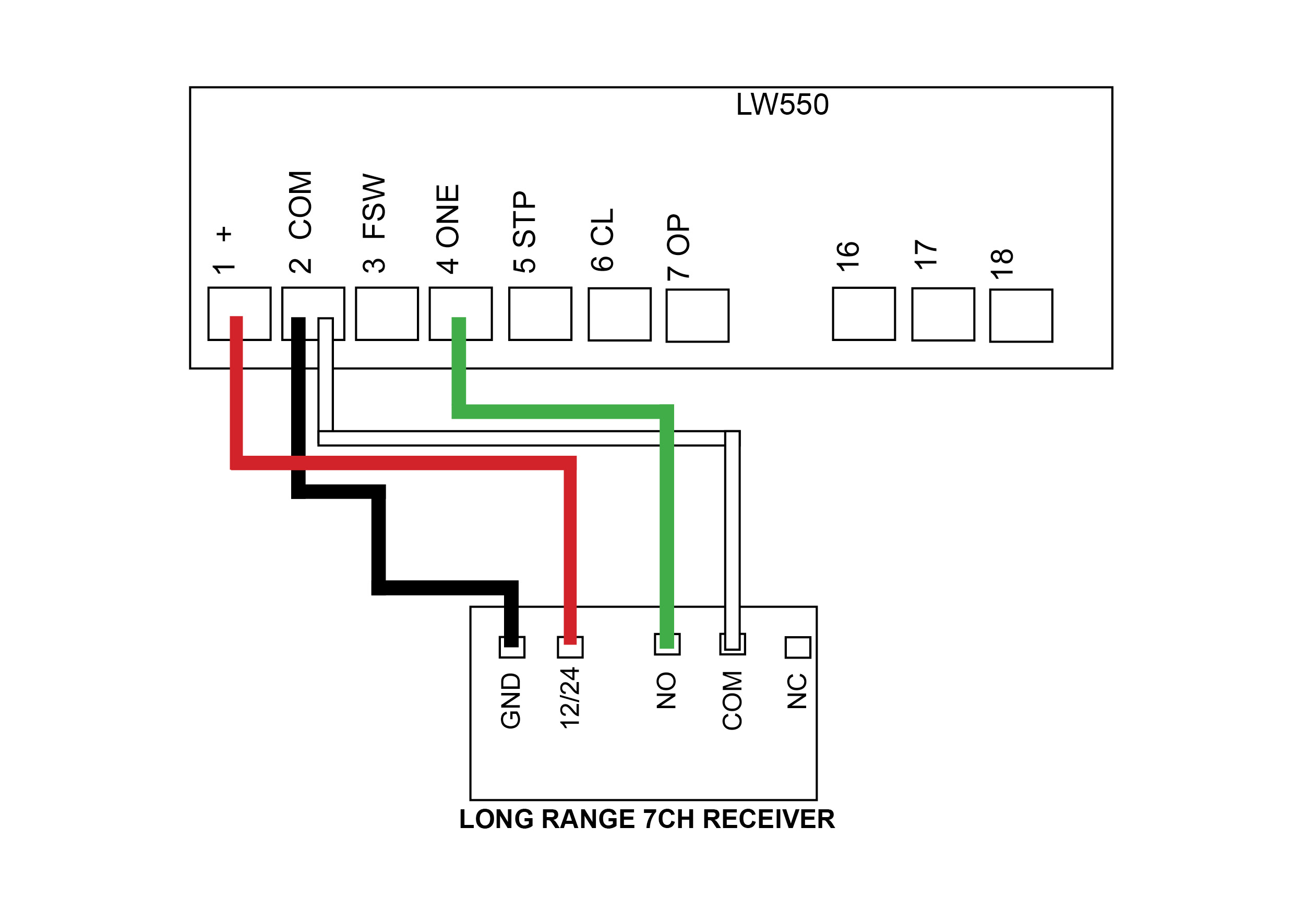
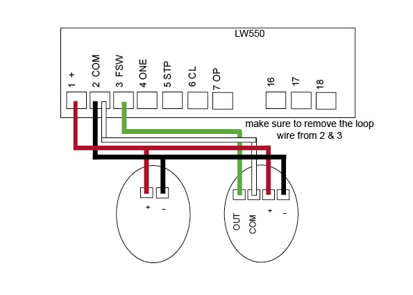
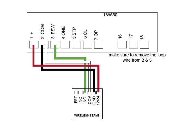
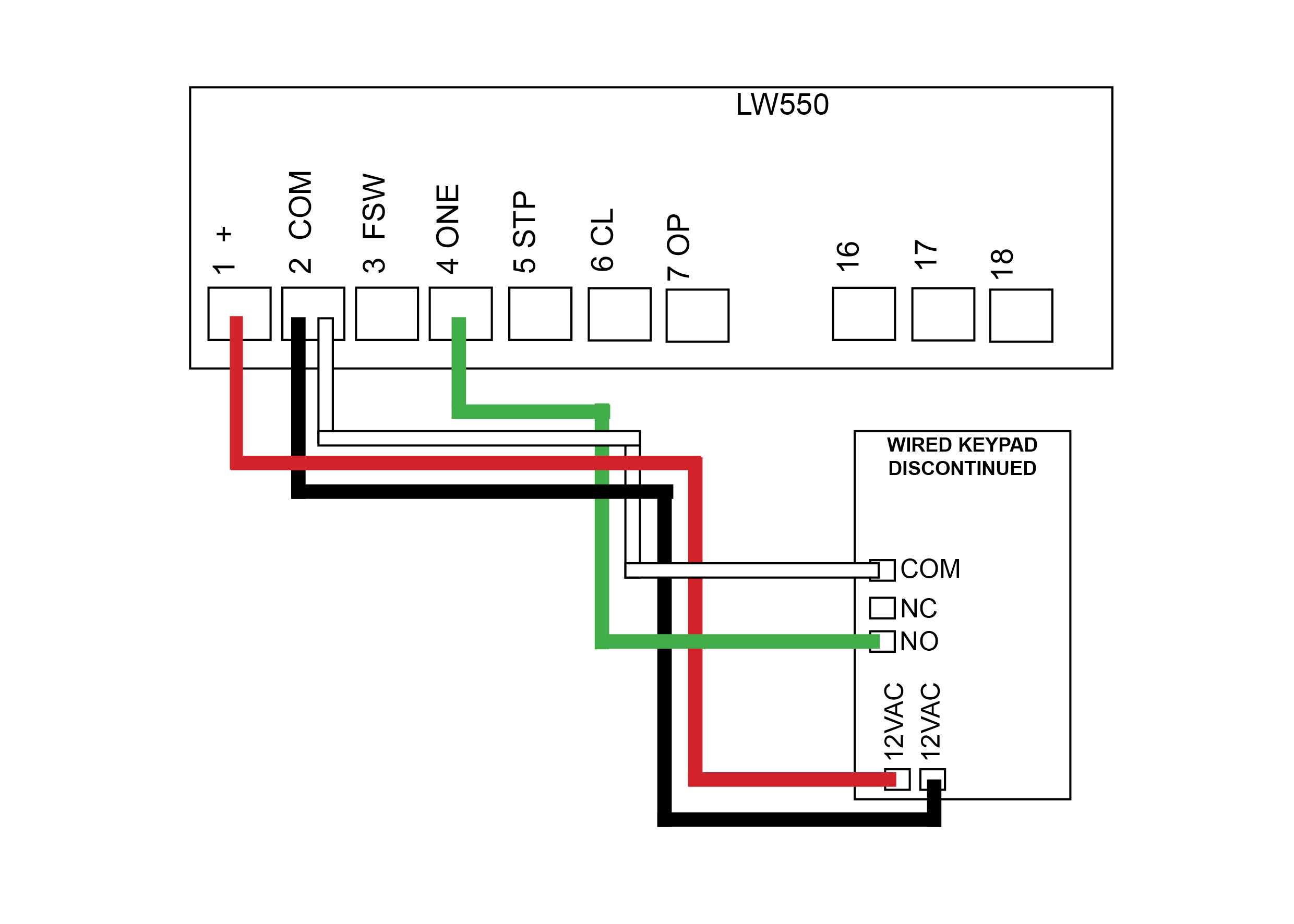
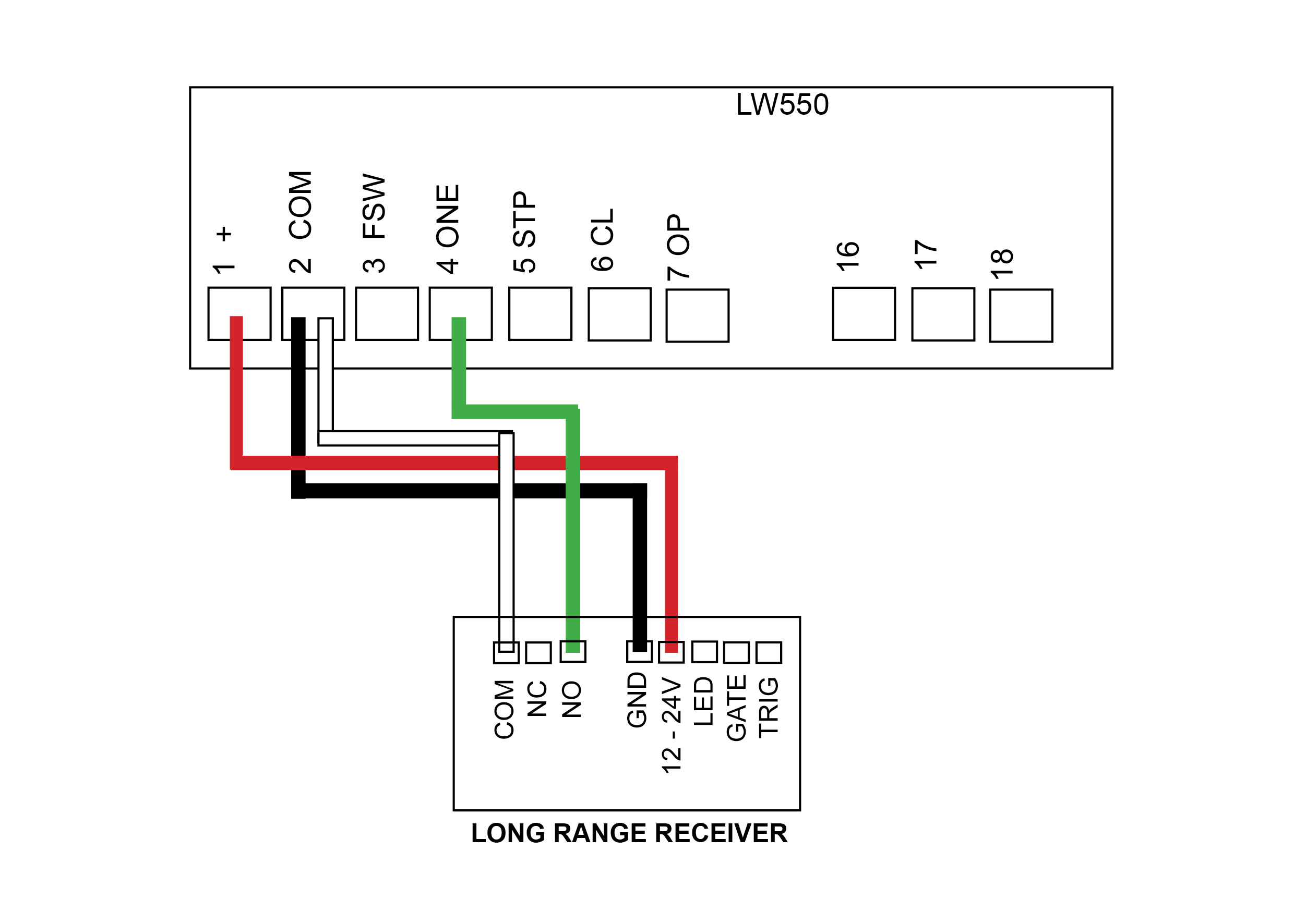
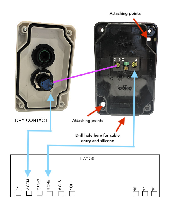
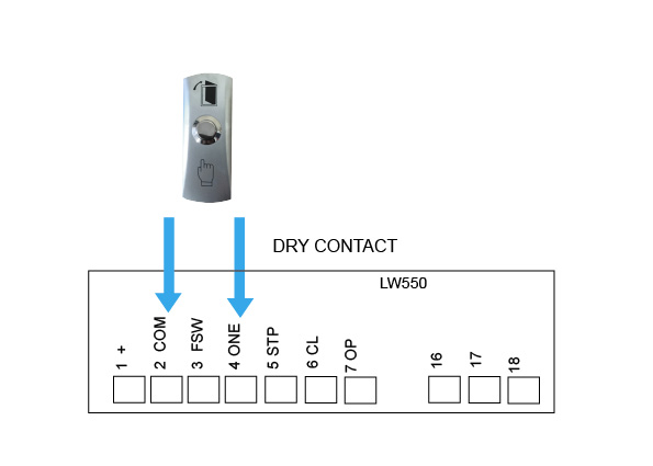
AC LW550
(discontinued)
Control Board
Troubleshoot this device
Pairing the KP Receiver to your device
1. Press P1 on the receiver board (red LED will go solid)
2. Press the device you are trying to tune and hold for 3 seconds (red LED will flash to say device and receiver are paired)
Deleting your device from the KP Receiver
Press P2 on the receiver board for 8 seconds (red LED will go solid, your device and KP receiver are now unpaired)
Wiring Diagrams
-
E8 - EGA Swing
Control Board
-
TMT 400LLS - Swing
Control Board
-
DACE Ultima
Control Board
-
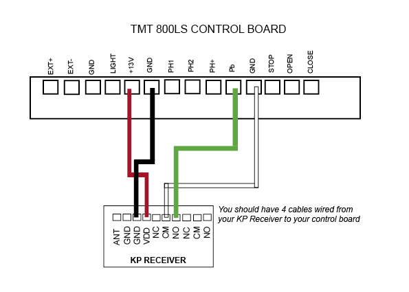
TMT 800LS
Control Board
-
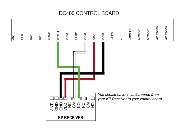
DC400
Control Board
-
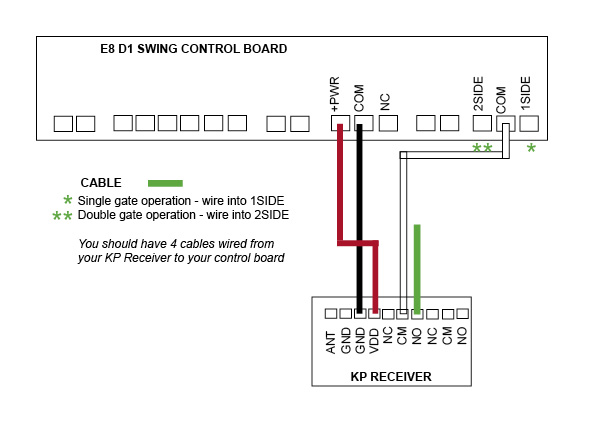
E8 - D1 Swing
(discontinued)
Control Board
-
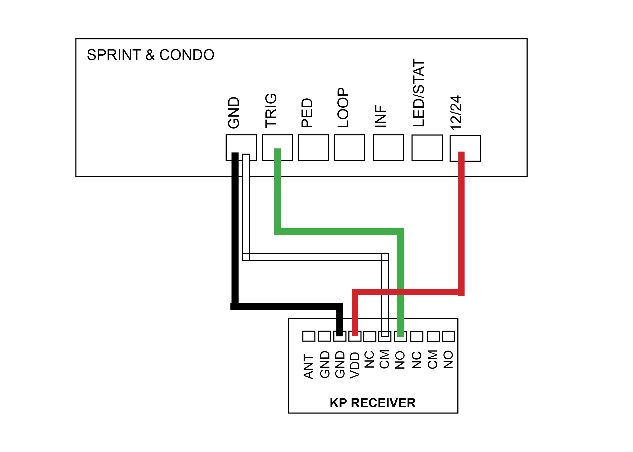
DACE Sprint/Condo
(discontinued)
Control Board
-
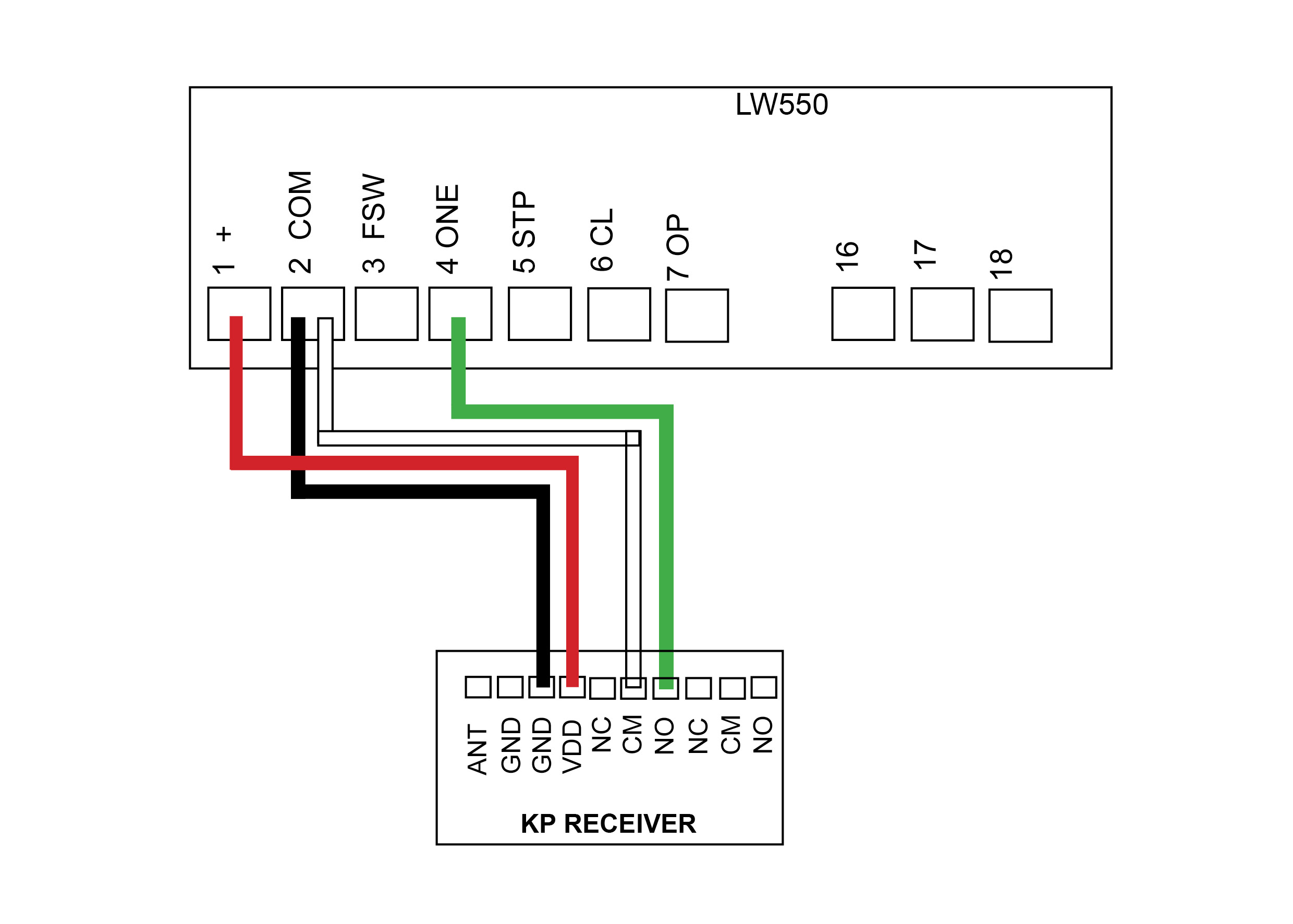
AC LW550
(discontinued)
Control Board
Troubleshoot this device
This receiver will have a Purple Antenna
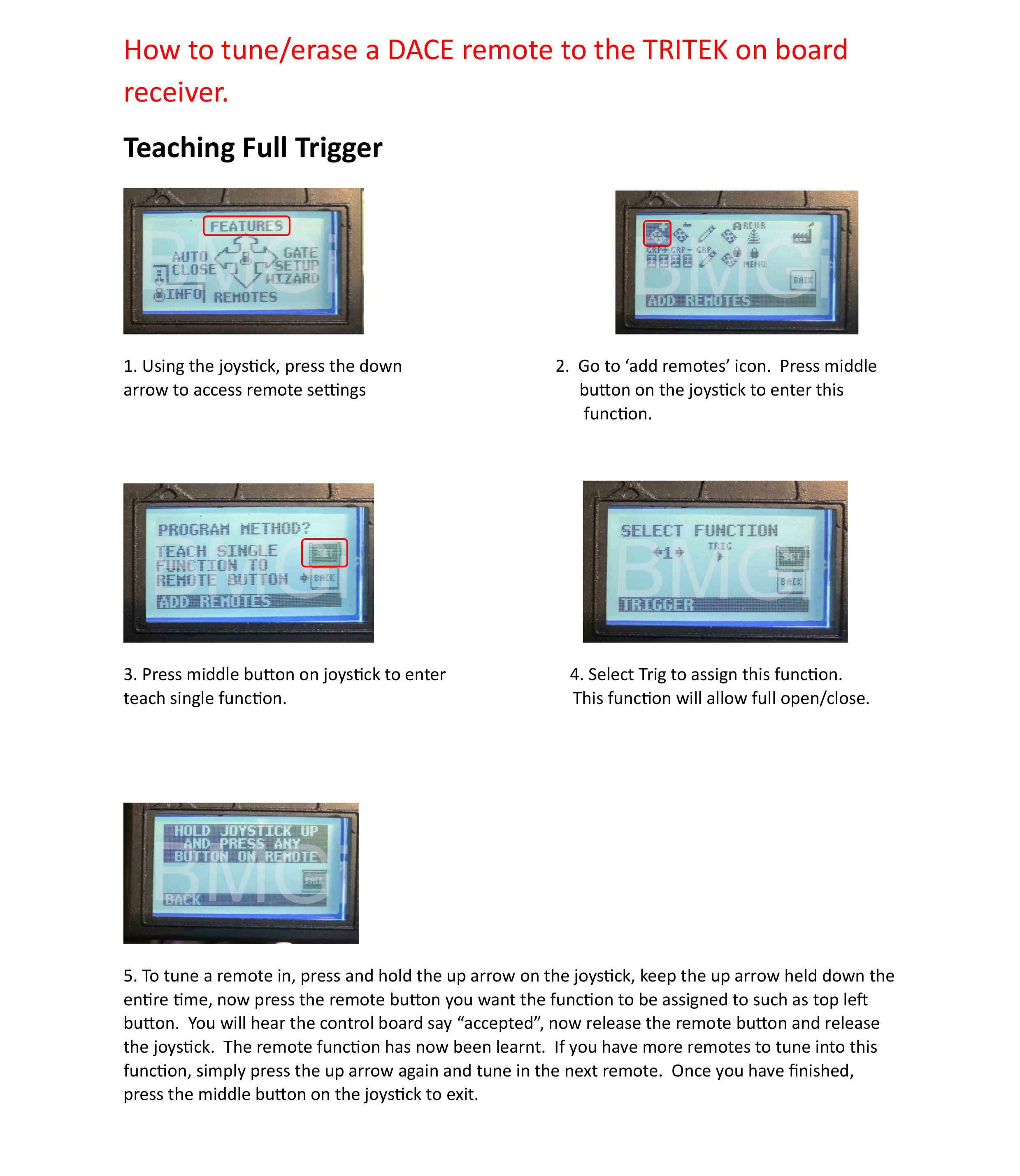
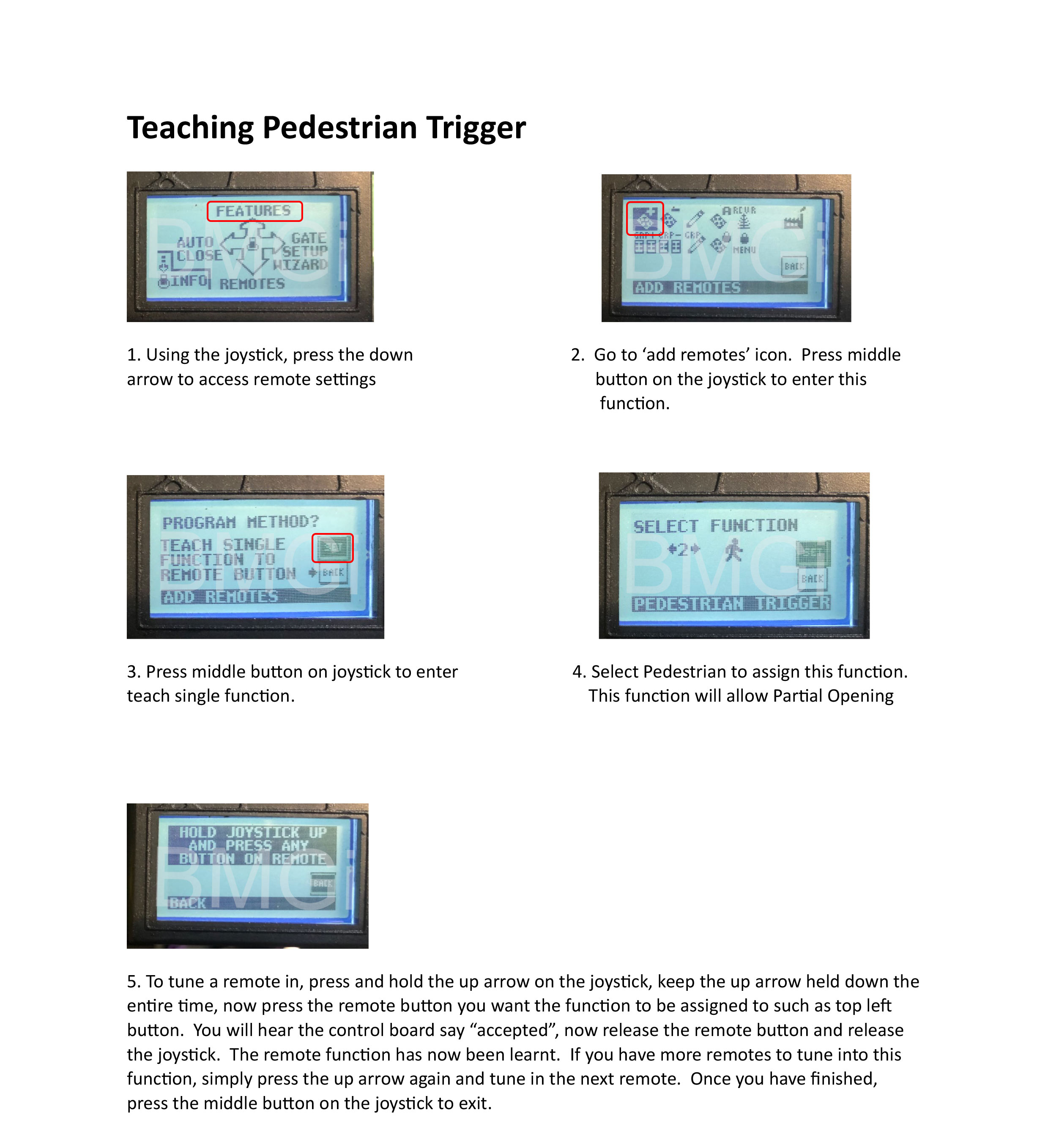
Programming a remote
- With the power connected to the receiver, place the black jumper link over the RELAY pins (if this is not already set).
- Press and hold the remote button to be programmed to the receiver. Wait for the green light on the receiver to flash quickly.
- While pressing the remote button, place the 2nd black jumper link over the REMOTE pins for 2 seconds (only) and then remove the black jumper link. Now test that the remote works.
- When finished, make sure to place the 2nd black jumper back on 1 pin only.

Erasing a single remote button from receiver
You will use the button that holds the position in the receiver immediately before the one that is to be erased!!
- With the power connected to the receiver, press and hold the button on the remote that was programmed to the receiver before the button that is to be erased.
- Place a link over the ERASE pins. The LED will flash twice and then remain solid.
- Release the remote button
- Remove the link.
The remote button is now erased from the receiver.
Erasing all remotes
- With the power connected to the receiver, place a link over the ERASE pins.
- The LED will flash ten times and then remain on solid.
- Remove the link.
The remote buttons have now been erased from the receiver.
MANUFACTURERS RECOMMENDATIONS AND COMMENTS
- For optimum range it is advisable to place the receiver a minimum of 2
metres vertically away from the gate motor e.g. top of gate posts.
- When placing the receiver outside of the control box or motor housing it is
important to use a weatherproof box with all entry points sealed. The standard
receiver housing is only splash proof and not suitable for outdoor applications. **
- Make sure there are no exposed wires outside the receiver.
- Placing the receiver inside the motor housing will reduce the range of the
receiver when the motor is in operation.
- Range may be affected by signals transmitted from another source.
- When coding remotes for use in a complex it is recommended that all
remotes be physically numbered and a record be kept.
* All dependent on line of sight to the gate and interference which may
reduce expected range. DO NOT ALTER THE ANTENNA IN ANY WAY (TUNED
LENGTH ANTENNA)
** Warranty will void if the receiver housing has been placed outside and not in a
recommended weatherproof box.
Tuning a wireless push button
Tuning a remote
Tuning a wireless keypad
Wiring Diagrams
-
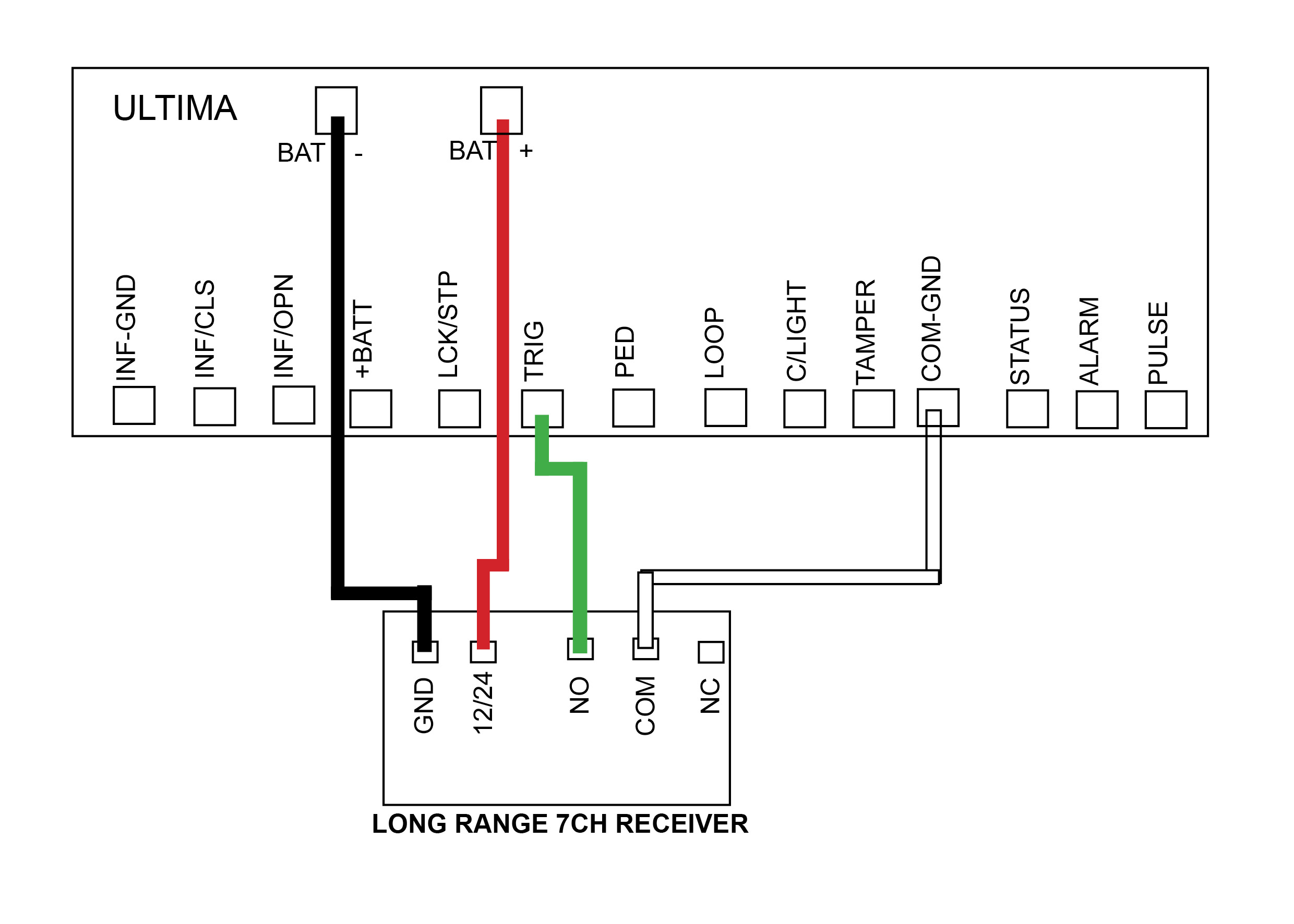
DACE Ultima
Control Board
-
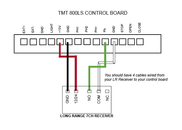
TMT 800LS
Control Board
-
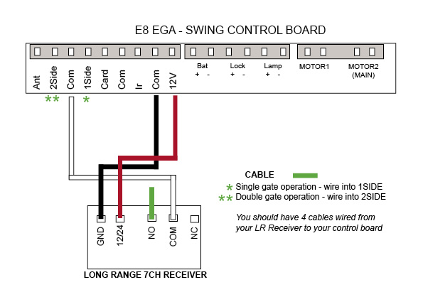
E8 - EGA Swing
Control Board
-
TMT 400LLS - Swing
Control Board
-
DC400
Control Board
-

E8 - D1 Swing
(discontinued)
Control Board
-

DACE Sprint/Condo
(discontinued)
Control Board
-
AC LW550
(discontinued)
Control Board
Troubleshoot this device
Unit Attaching Points
We recommend attaching the push button via the attaching points as indicated with a red arrow shown in the image.
When you attach the push button unit to your post, even though the button housing is a sealed unit, we highly recommend sealing (silcone) all the way around the back housing to prevent any water or insects entering in through your screws.
The battery required for this device is a 12v 27A
We recommend every 6-12 months to do a thorough check over the push button and it’s internals to make sure there is no insect infestation and that everything is still in good working order.
Please be aware that failure to perform the recommendations above will void your warranty.

Only wireless push buttons purchased from July 2022 and onwards are able to tune to the E8-EGA control board and Ultima kits

Tuning to the swing EGA control board
Tuning to the DACE Ultima board - Use the KP receiver on solar
Tuning to a long range receiver
Tuning to the KP receiver
This receiver will have a Purple Antenna
Programming a button
- With the power connected to the receiver, place the black jumper link over the RELAY pins (if this is not already set).
- Press and hold the button to be programmed to the receiver. Wait for the green light on the receiver to flash quickly.
- While pressing the button, place the 2nd black jumper link over the REMOTE pins for 2 seconds (only) and then remove the black jumper link. Now test that the remote works.
- When finished, make sure to place the 2nd black jumper back on 1 pin only.
Erasing all buttons
Note: deleting an accessory from this receiver will delete all accessories tuned in. You will be required to tune any other items back in that you still require.
- With the power connected to the receiver, place a link over the ERASE pins.
- The LED will flash ten times and then remain on solid.
Remove the link.
The buttons have now been erased from the receiver.

Unit Attaching Points
We recommend attaching the push button via the attaching points as indicated with a red arrow shown in the image.
When you attach the push button unit to your post, even though the button housing is a sealed unit, we highly recommend sealing (silcone) all the way around the back housing to prevent any water or insects entering in through your screws.
We recommend every 6-12 months to do a thorough check over the push button and it’s internals to make sure there is no insect infestation and that everything is still in good working order.
Please be aware that failure to perform the recommendations above will void your warranty.
LONG RANGE RECEIVER - MANUFACTURERS RECOMMENDATIONS AND COMMENTS
1. For optimum range it is advisable to place the receiver a minimum of 2
metres vertically away from the gate motor e.g. top of gate posts.
2. When placing the receiver outside of the control box or motor housing it is
important to use a weatherproof box with all entry points sealed. The standard
receiver housing is only splash proof and not suitable for outdoor applications. **
3. Make sure there are no exposed wires outside the receiver.
4. Placing the receiver inside the motor housing will reduce the range of the
receiver when the motor is in operation.
5. Range may be affected by signals transmitted from another source.
* All dependent on line of sight to the gate and interference which may
reduce expected range. DO NOT ALTER THE ANTENNA IN ANY WAY (TUNED
LENGTH ANTENNA)
** Warranty will void if the receiver housing has been placed outside and not in a
recommended weatherproof box.
Tuning a push button to the long range receiver - Purple Antenna
Wiring Diagrams
-
E8 - EGA Swing
Control Board
-
TMT 400LLS - Swing
Control Board
-
DC400
Control Board
-
TMT 800LS
Control Board
-
DACE Ultima
Control Board
-
E8 - D1 Swing
(discontinued)
Control Board
-
DACE Sprint/Condo
(discontinued)
Control Board
-
AC LW550
(discontinued)
Control Board
Troubleshoot this device
If you require extra security on your keypad, then it is recommended that you change the factory program code (0000) to a secure code which you must make note of. Failing to make note of your new program code will prevent you from being able to add or delete pin codes in the future. You would then be required to perform the 'Keypad reset'.
Factory pin code in the keypad to start off with is 1111#. When entering in your first pin code the factory pin code will be wiped.

OLD MODEL
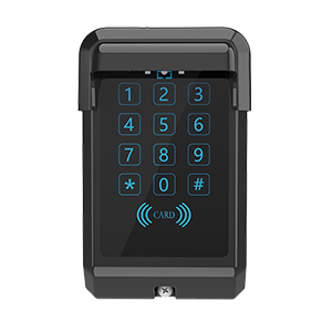
NEW MODEL (END 2024)
Important:
New model keypads from late April 2025 will now be compatible with our TMT Kits.
Details below will show you how to switch the keypad between (factory setting) E8 and DACE kits to the TMT kits.
To work with E8 and DACE kits
- Enter program code (Factory 0000) then press *
- Press 7 7 #
- Press 0 1 #
To work with BMG's TMT kits
- Enter program code (Factory 0000) then press *
- Press 7 7 #
- Press 0 2 #
Setting up a 4 digit pin code in your keypad
- Enter program code (Factory 0000) then press *
- Press 0 1 #
- Enter your pin code = ? ? ? ? # (pin code now entered)
Setting up Swipe Card or Tag (NEW MODEL ONLY)
- Enter program code (Factory 0000) then press *
- Press 0 1 #
- Swipe card or tag then press #
Delete a single pin code from the keypad
- Enter program code (Factory 0000) then press *
- Press 5 8 #
- Enter 4 digit pin number # that you want to delete (keypad will give 1
long beep followed by a short beep to indicate the pin code deleted)
Erasing all pin codes from the keypad
- Enter your program code (Factory is 0000) then press *
- Press 0 0 #
- Now all pin codes will be wiped and set back to the factory pin code 1111#
Battery test
- Enter program code (Factory 0000) then press *
- Press 8 9 # (battery is OK with a long beep or if battery is low there will
be a short beep and the red LED indicator will show)
Turn off/on keypad backlight
- Enter program code (Factory 0000) then press *
- Press 3 9 #
RF Signal Delay (NEW MODEL ONLY)
This is used if you are having trouble tuning the keypad to a receiver and you need the delay extended to allow the keypad to tune.
- Enter program code (Factory 0000) then press *
- Press 41 # (keypad will sound a long beep)
- Select on of the following
01#=.5sec delay
02#=1sec delay
03#=1.5sec delay
04#=2sec delay
- Now try tuning your keypad to the receiver.
10 Second Continuous Signal
This is used if you are having trouble tuning the keypad to a device and require a longer signal.
- Enter program code (Factory 0000) then press *
- Press 55 # (keypad will sound a long beep)
- Press 01 # (if using channel 2 press 02 #)
- Now proceed to tune keypad to your device
Keypad resetting (OLD MODEL KEYPAD)
- Remove the keypad from weather shield
- Your keypad should now be awake with the alarm activated
- While the keypad alarm is going off, press the reset button located on top of the keypad for 5 seconds until all LED lights come on
- Now release the reset button, resetting is now complete (all keypad codes
will be cleared and reset to factory)
- Place the keypad back into the weather shield
The keypad will now be reset to 0000 program code and 1111 factory pin code.
Keypad resetting (NEW MODEL)
Remove the button dust plug from the back case, use a small pin or other object to press and hold the button for about 10 seconds, the buzzer will sound a long beep, the reset operation is successful. Now all pin codes and parameters are reset to factory default and all pin codes and swing cards/tags have been deleted.
Security lock mode
When the keypad enters the programming mode or transmits an RF signal the keypad allows up to 4 incorrect attempts. When an incorrect pin code is entered for the 5th time the blue light will stay on and the keypad will be locked for 2 minutes. This prevents illegal users from trying to open the gate via the pin code. The keypad unlocks automatically after 2 mintues.
Changing the 4 digit ‘program code’ (0000)
Your program code only requires to be changed if you require extra security on your keypad. You will need to take note of your program code as this will be used to add or delete pin codes in the future.
- Enter program code = 0 0 0 0 *
- Press 6 9 #
- Enter new 4 digit program mode code #
Did your keypad come with a receiver? If yes then follow the links below for wiring instructions

Wiring diagram for the LR 7CH Receiver
View here
Watch our videos below to help with programming
and tuning your keypad to the correct device
How to add a pin number
How to tune change your programming code
How to tune your keypad to the KP Receiver
How to tune your keypad to the E8 EGA Board
How to tune your keypad to the LR Receiver
How to tune your keypad to the Ultima (Electric)
If you require extra security on your keypad, then it is recommended that you change the factory program code (0000) to a secure code which you must make note of. Failing to make note of your new program code will prevent you from being able to add or delete pin codes in the future. You would then be required to perform the 'Keypad reset'.
Factory pin code in the keypad to start off with is 1111#. When entering in your first pin code the factory pin code will be wiped.
Old Model
New Model (2025)
Pairing the receiver to the wireless keypad
- Press P1 on the receiver board (red LED will go solid)
- Enter your pin code = ? ? ? ? # (red LED will flash to say keypad and
receiver are paired)
Deleting KP recevier memory
- Press P2 on the receiver board for 8 seconds (red LED will go solid,
keypad and receiver now unpaired)
Setting up a 4 digit pin code in your keypad
- Enter program code (factory 0000) then press *
- Press 0 1 #
- Enter your pin code = ? ? ? ? # (pin code now entered)
Setting up Swipe Card or Tag (NEW MODEL ONLY)
- Enter program code (Factory 0000) then press *
- Press 0 1 #
- Swipe card or tag then press #
Delete a single pin code from the keypad
- Enter program code (factory 0000) then press *
- Press 5 8 #
- Enter 4 digit pin number that you want to delete (keypad will give 1
long beep followed by a short beep to indicate the pin code deleted)
Erasing all pin codes from the keypad
- Enter your program code (Factory is 0000) then press *
- Press 0 0 #
- Now all pin codes will be wiped and set back to the factory pin code 1111#
Turn off/on keypad backlight
- Enter program code (factory 0000) then press *
- Press 3 9 #
Battery test
- Enter program code (factory 0000) then press *
- Press 8 9 # (battery is OK with a long beep or if battery is low there will
be a short beep and the red LED indicator will show)
RF Signal Delay (NEW MODEL ONLY)
This is used if you are having trouble tuning the keypad to a receiver and you need the delay extended to allow the keypad to tune.
- Enter program code (Factory 0000) then press *
- Press 41 # (keypad will sound a long beep)
- Select on of the following
01#=.5sec delay
02#=1sec delay
03#=1.5sec delay
04#=2sec delay
- Now try tuning your keypad to the receiver.
10 Second Continuous Signal
This is used if you are having trouble tuning the keypad to a device and require a longer signal.
- Enter program code (Factory 0000) then press *
- Press 55 # (keypad will sound a long beep)
- Press 01 # (if using channel 2 press 02 #)
- Now proceed to tune keypad to your device
Keypad resetting (OLD MODEL KEYPAD)
- Remove the keypad from weather shield
- Your keypad should now be awake with the alarm activated
- While the keypad alarm is going off, press the reset button located on top of the keypad for 5 seconds until all LED lights come on
- Now release the reset button, resetting is now complete (all keypad codes
will be cleared and reset to factory)
- Place the keypad back into the weather shield
The keypad will now be reset to 0000 program code and 1111 factory pin code.
Keypad resetting (NEW MODEL)
Remove the button dust plug from the back case, use a small pin or other object to press and hold the button for about 10 seconds, the buzzer will sound a long beep, the reset operation is successful. Now all pin codes and parameters are reset to factory default and all pin codes and swing cards/tags have been deleted.
Security lock mode
When the keypad enters the programming mode or transmits an RF signal the keypad allows up to 4 incorrect attempts. When an incorrect pin code is entered for the 5th time the blue light will stay on and the keypad will be locked for 2 minutes. This prevents illegal users from trying to open the gate via the pin code. The keypad would unlocks automatically after 2 mintues.
Changing the 4 digit ‘program code’ (0000)
Your program code only requires to be changed if you require extra security on your keypad. You will need to take note of your program code as this will be used to add or delete pin codes in the future.
- Enter program code = 0 0 0 0 *
- Press 6 9 #
- Enter new 4 digit program mode code #
How to tune the wireless keypad to the KP Receiver
How to add a pin number
Wiring Diagrams
If you have a motor which has not been supplied by BMGI you will need to follow the wiring manual supplied for your kit on wiring an external receiver. The wiring diagrams below are for BMGi's motors only.
-
E8 - EGA Swing
Control Board
-
TMT 400LLS - Swing
Control Board
-
DACE Ultima
Control Board
-
TMT 800LS
Control Board
-
DC400
Control Board
-
E8 - D1 Swing
(discontinued)
Control Board
-
DACE Sprint/Condo
(discontinued)
Control Board
-
AC LW550
(discontinued)
Control Board


