The Transmitter is fitted with a RED LED which indicates when the power is on.
The receiver is fitted with a RED LED which indicates when the beams are aligned.
2. Manufacturers Comments:
It is recommended that beams be sealed with silicone rubber once they are closed.
Beams can be affected by florescent lights. It is not recommended that the beams be placed in direct view of florescent pillar lights.
The range of the beams can be affected by environmental conditions. Rain, mist etc can reduce the range of the beams.
Ensure that the power is disconnected before wiring the beams.
3. Fitting Beams to the Gate Post:
Beams should be placed around 700mm high above the ground level. The transmitter and receiver must, however, be aligned along a visual (and level) axis.
If aligning the beams over a distance greater than 20m it is necessary that the covers be replaced in order to achieve alignment.
Remove the PC Boards from both transmitter and receiver units.
Place the housing backing against the pillar at the prescribed spot and scribe through the screw holes.
Drill at the scribed marks using a 5mm masonry drill.
Attach the housing backing to the wall using the supplied fasteners and 'O' ring. Ensure that the 'O' ring is fitted to the top fastener.
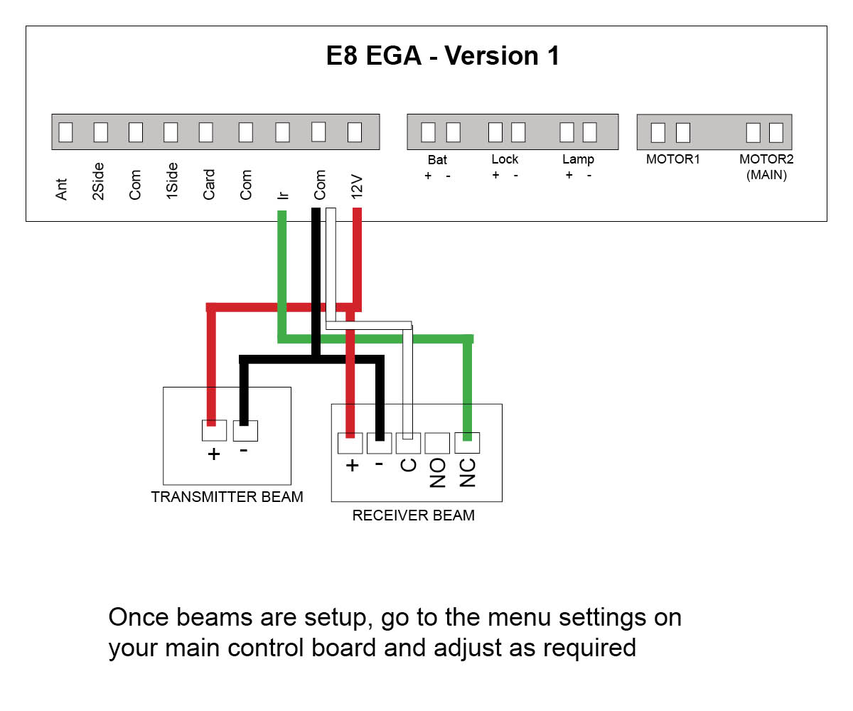
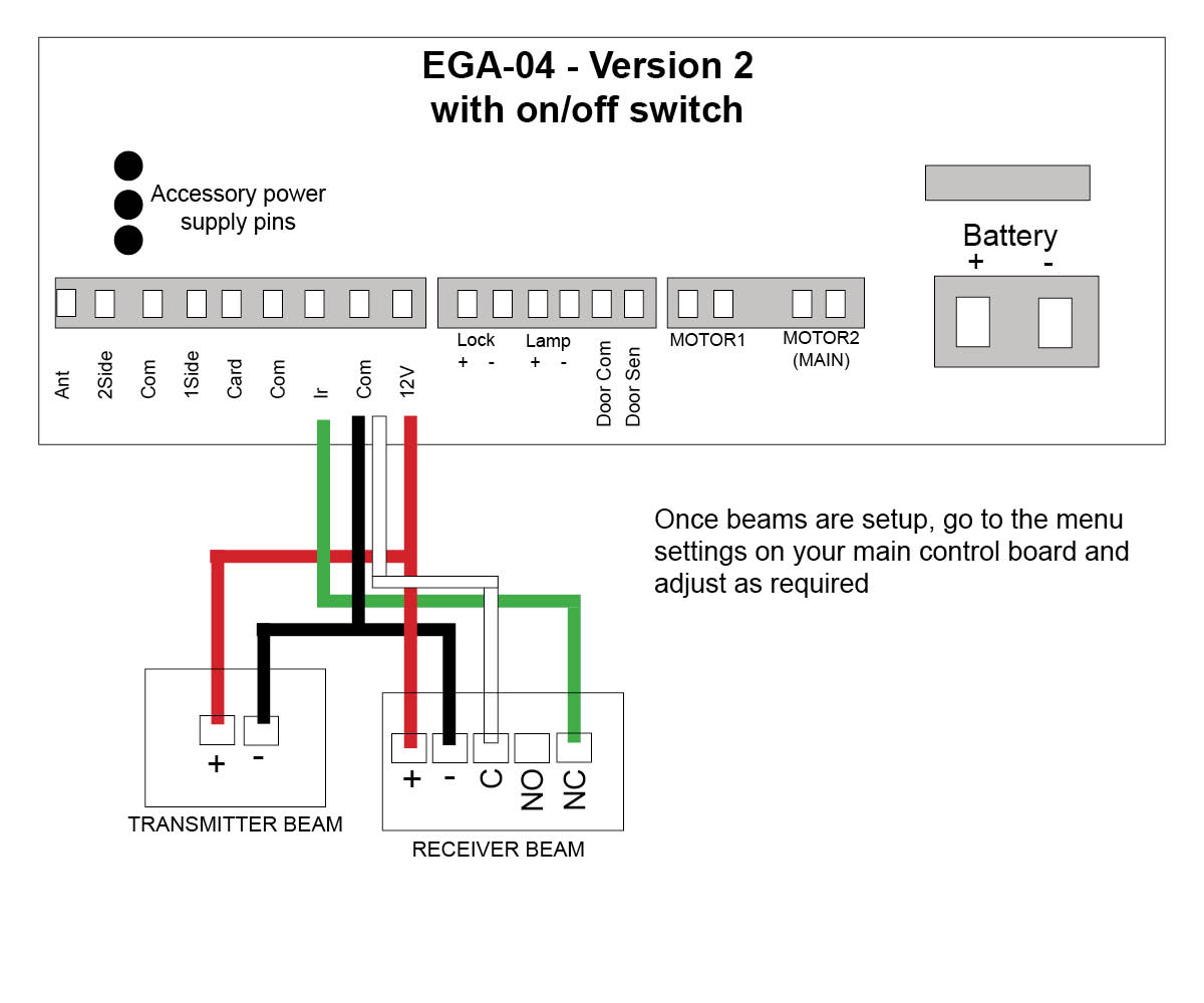
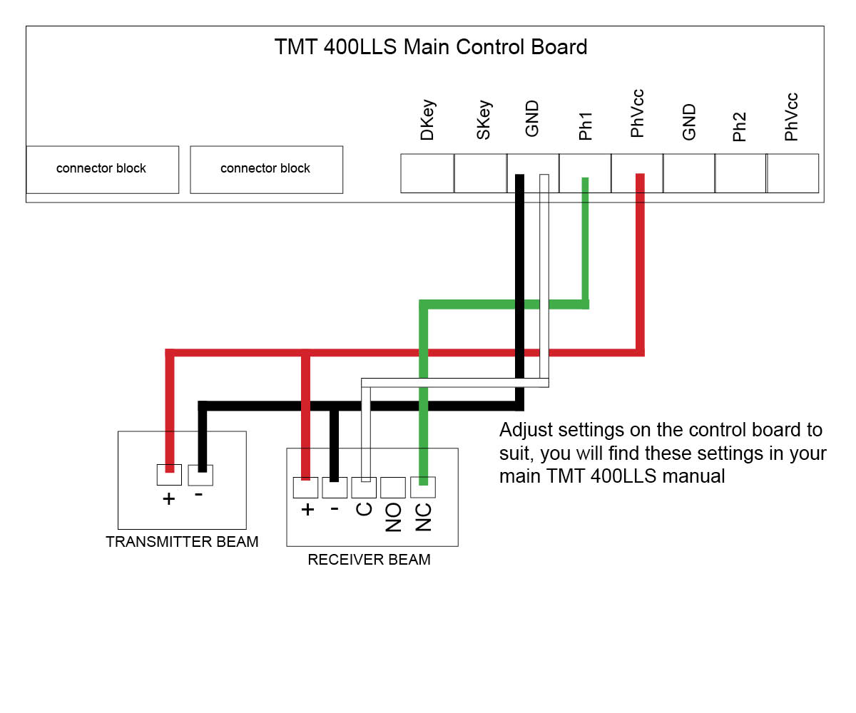
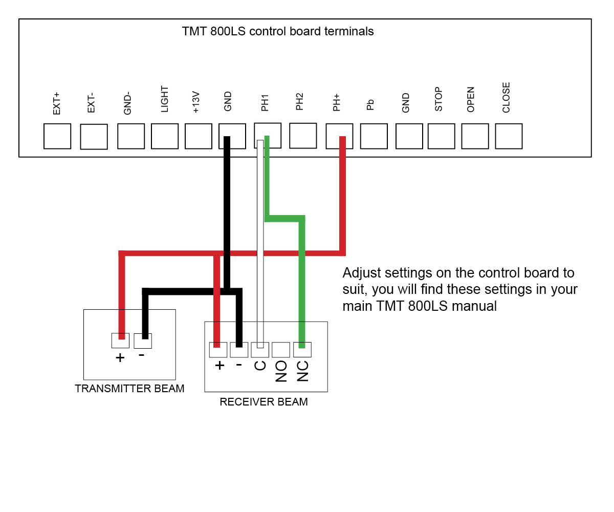
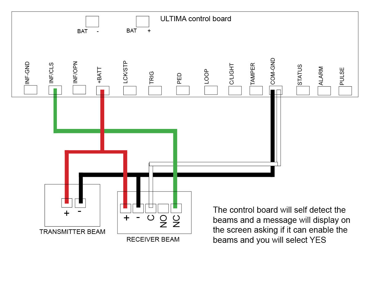
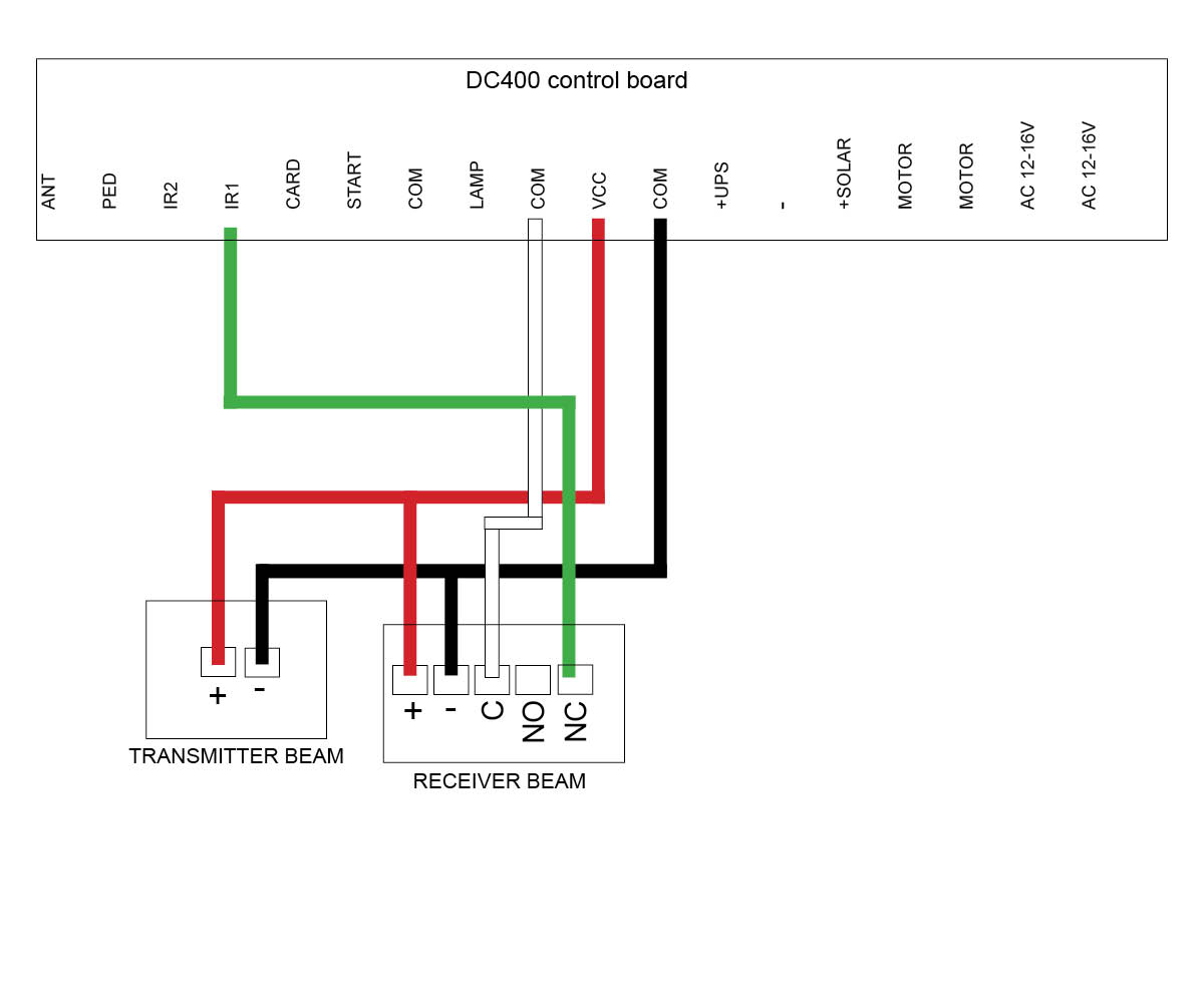
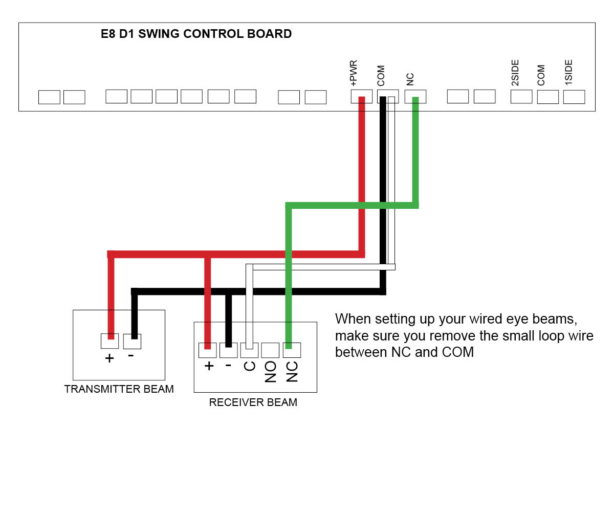
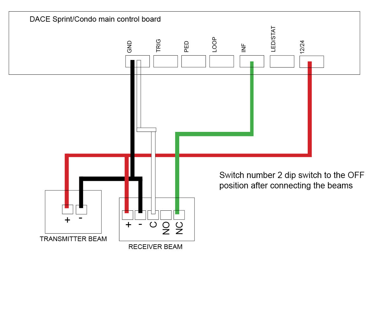
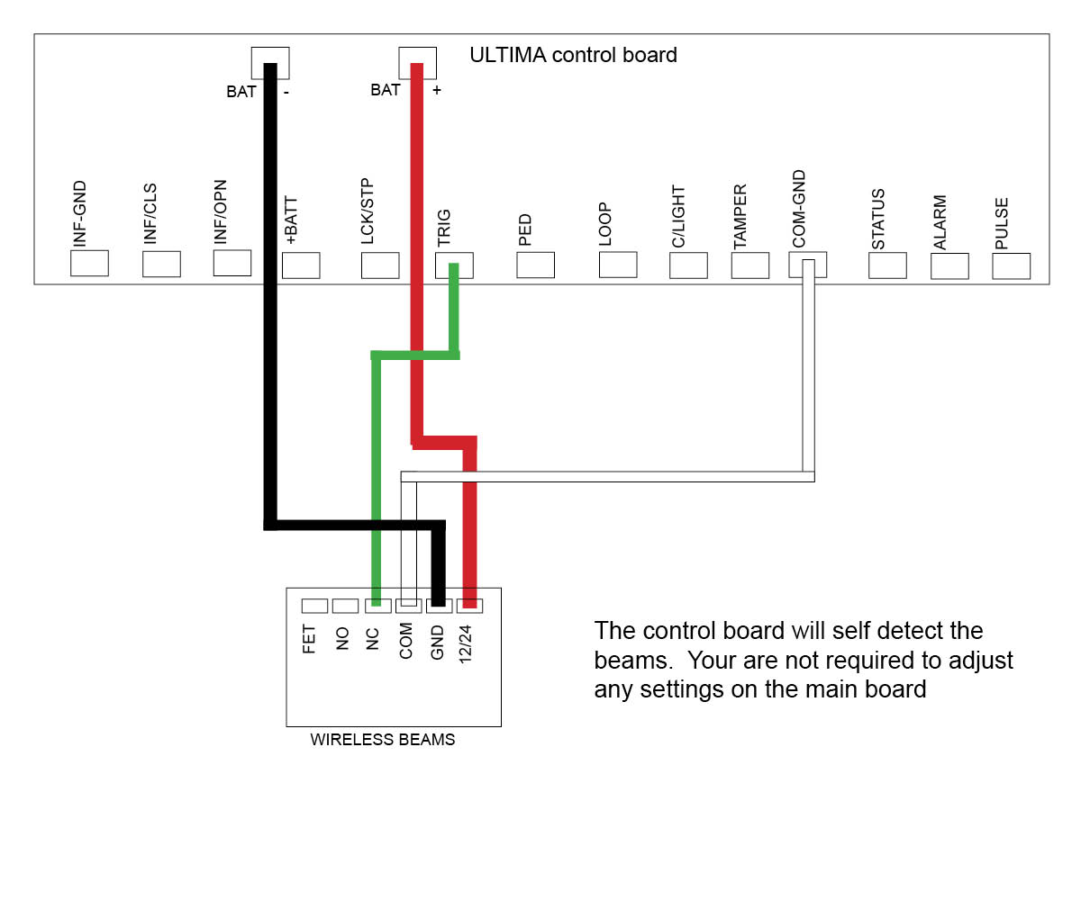
Replace the PC Boards and follow wiring instructions as per gate motor manual or BMGs wiring guides below.
4. Technical Specifications:
Power Supply: 12V-24V DC/AC
Max. Distance: 40m
Output Contact Rating: 5A at 220V AC
Click on the motor you have below to see the wiring diagram:
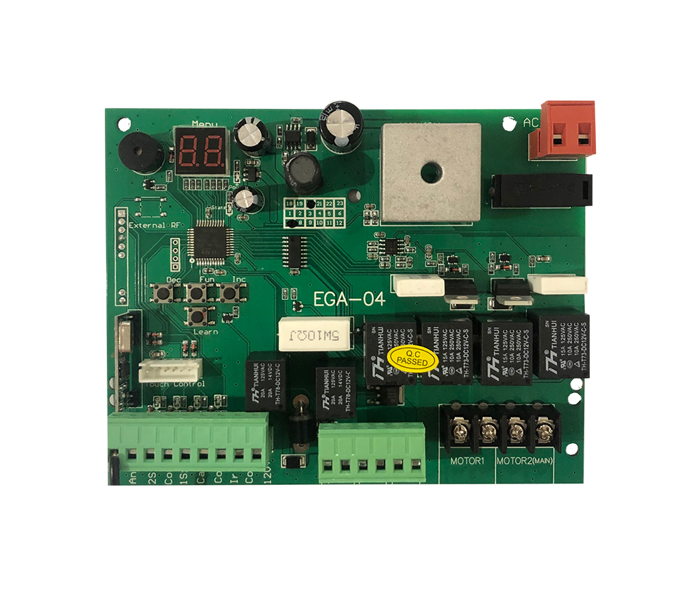
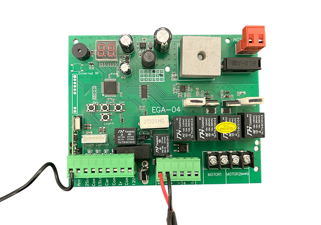
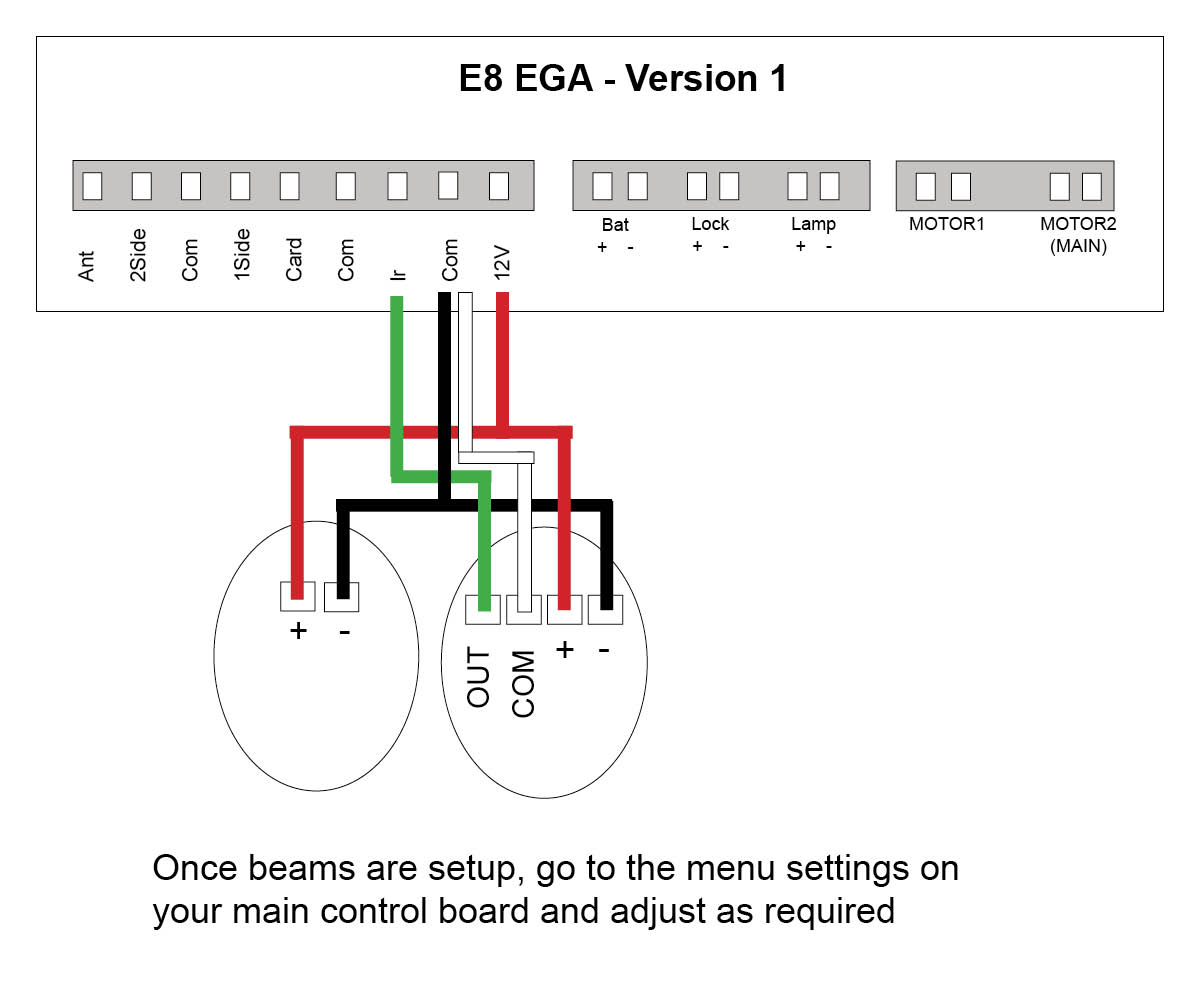
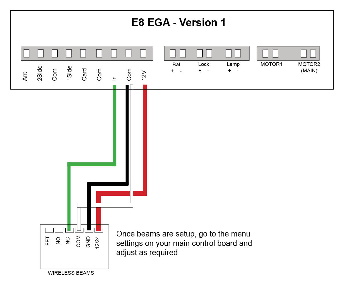
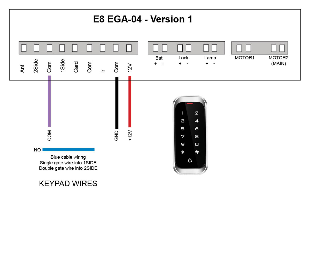
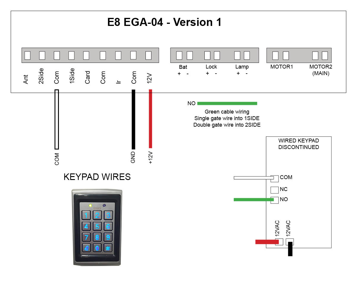
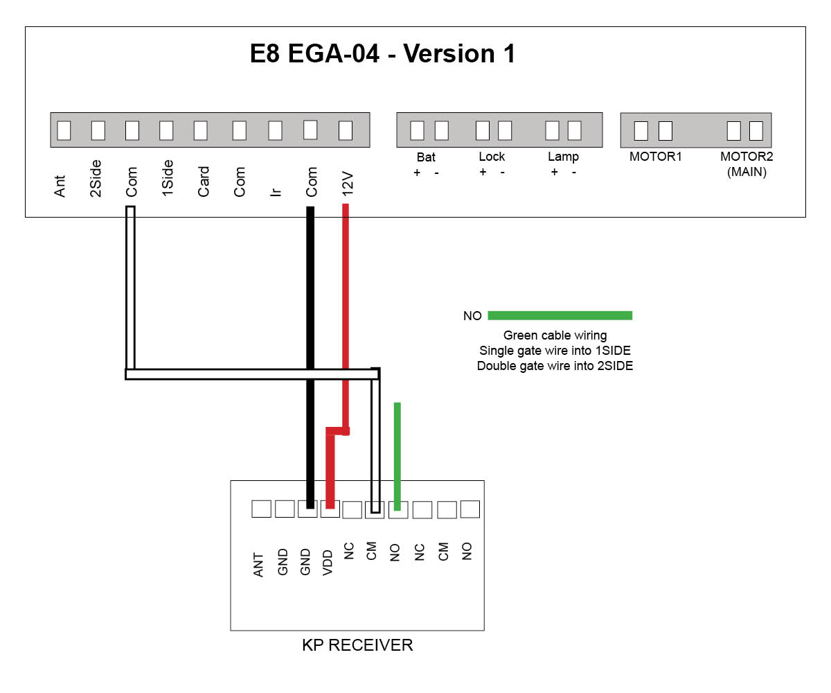
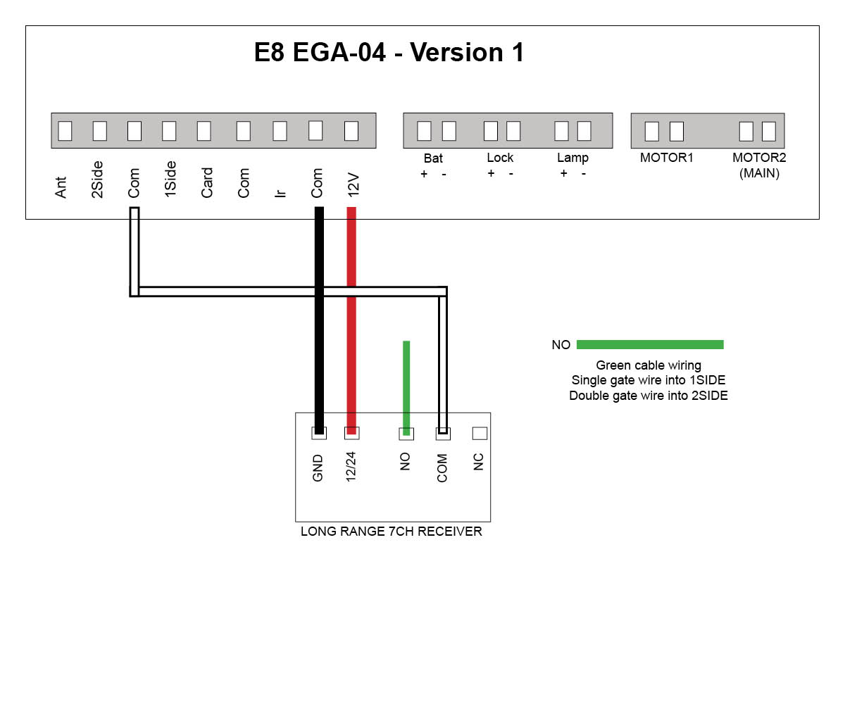
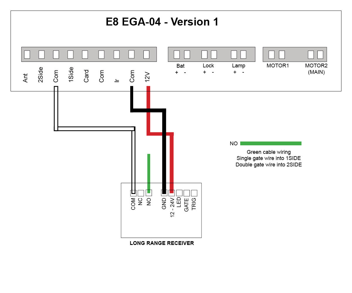
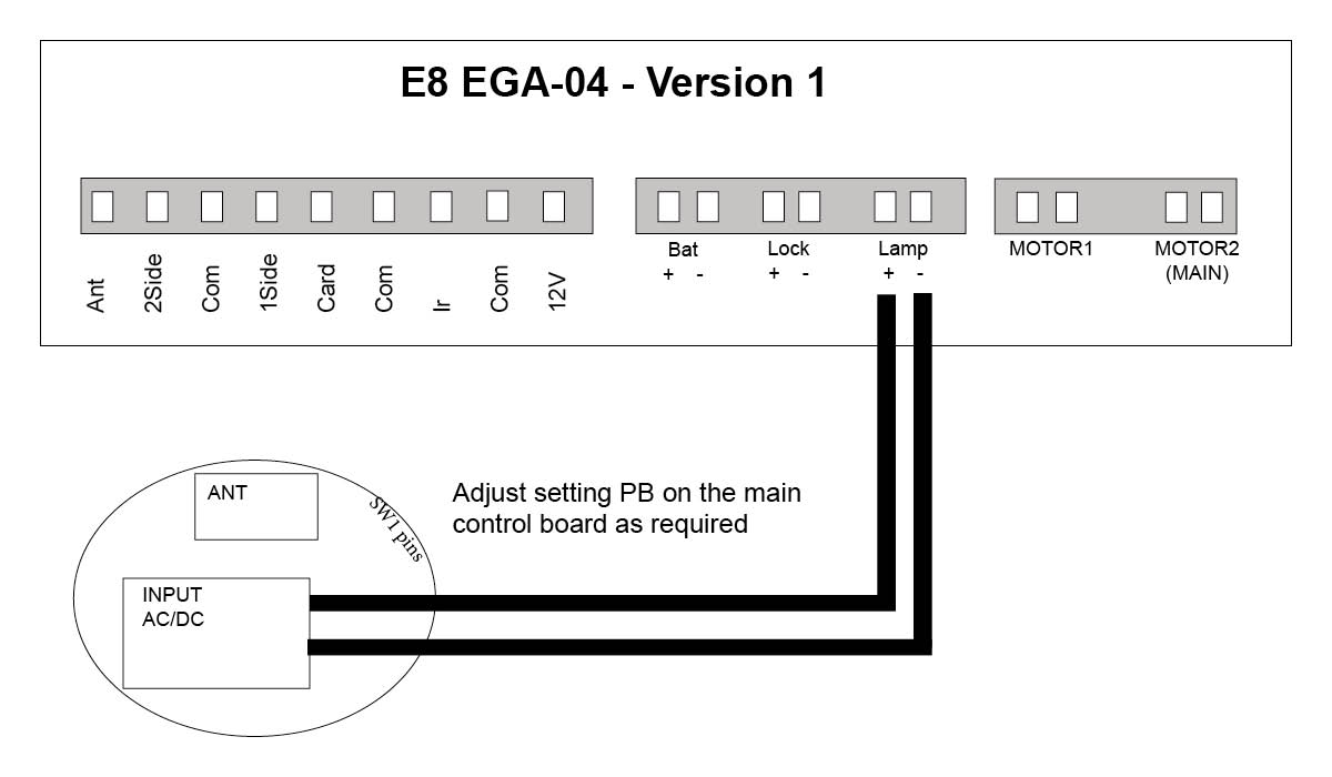
E8 Swing motor - EGA-04 version 1 board
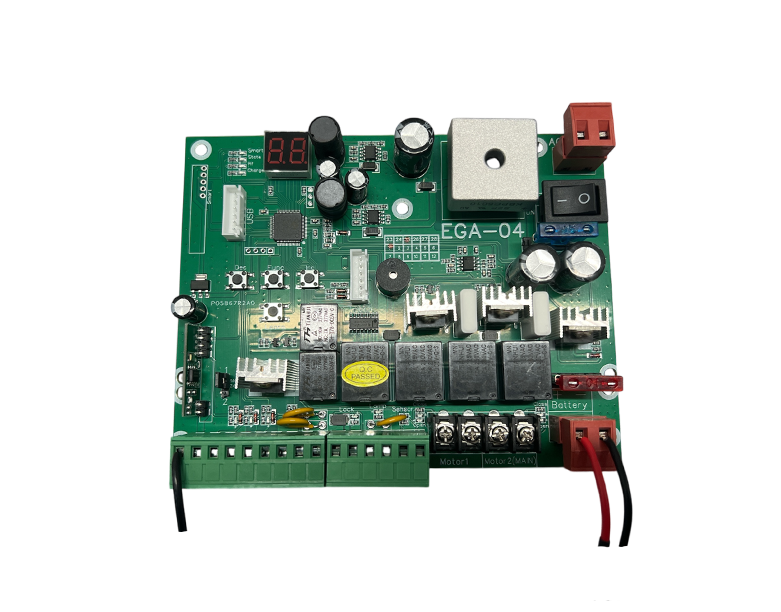
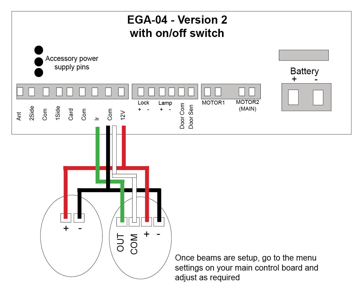
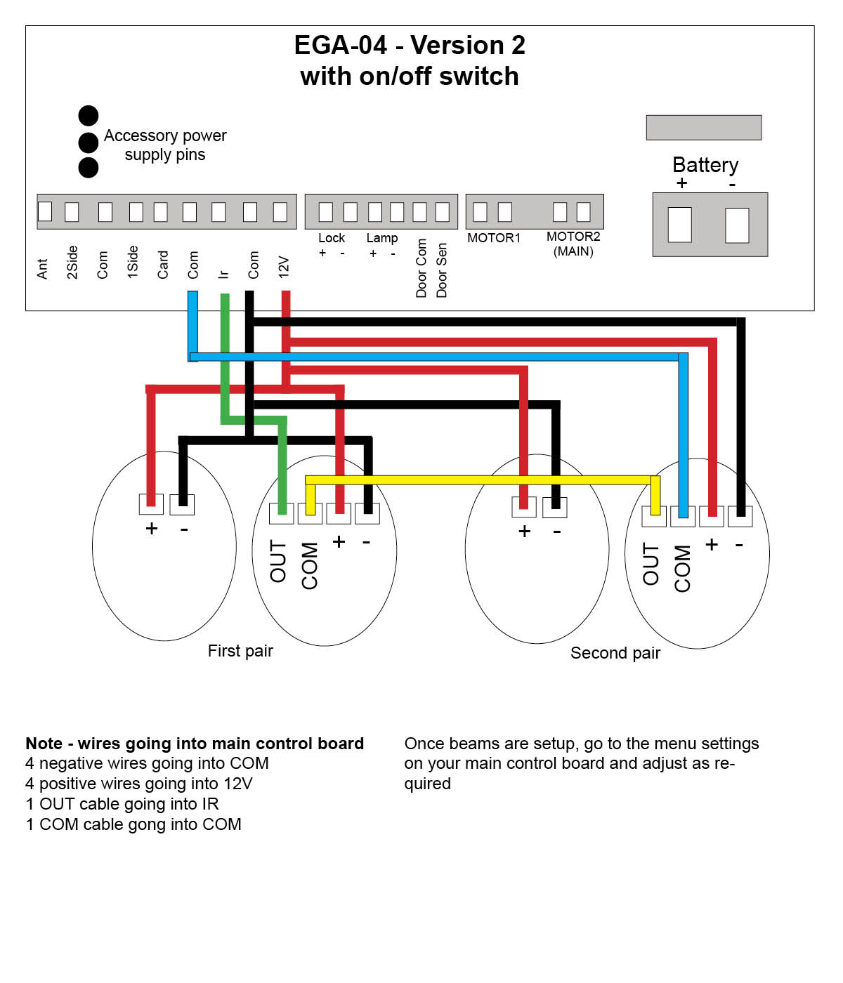
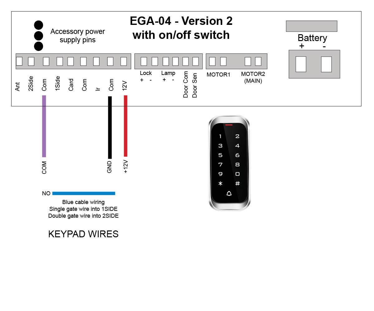
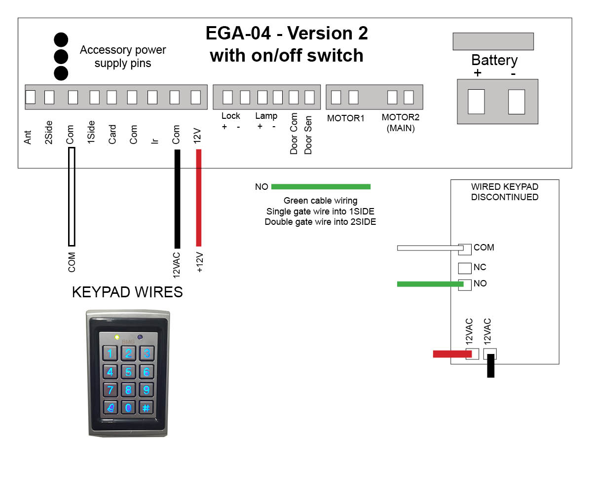
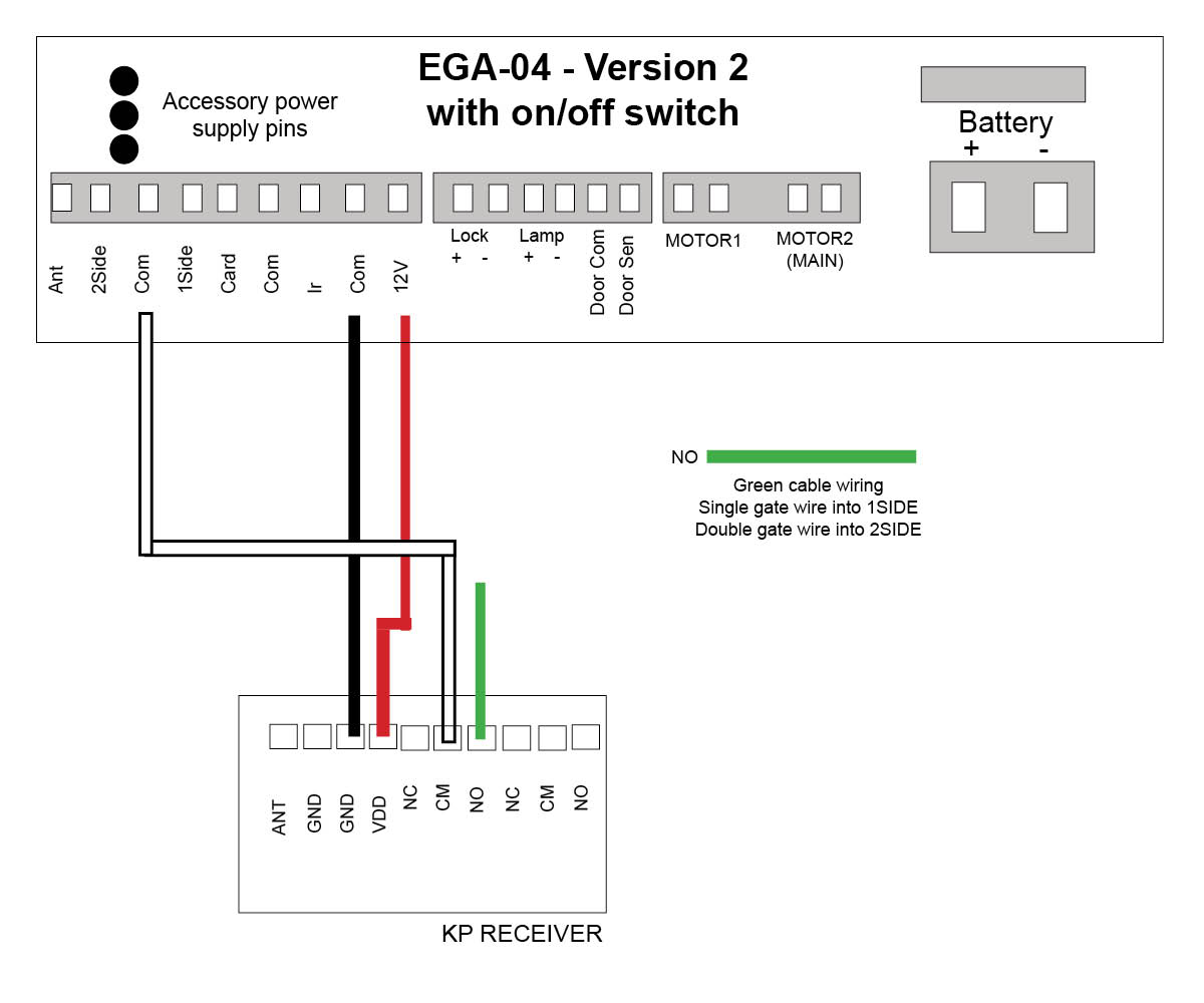
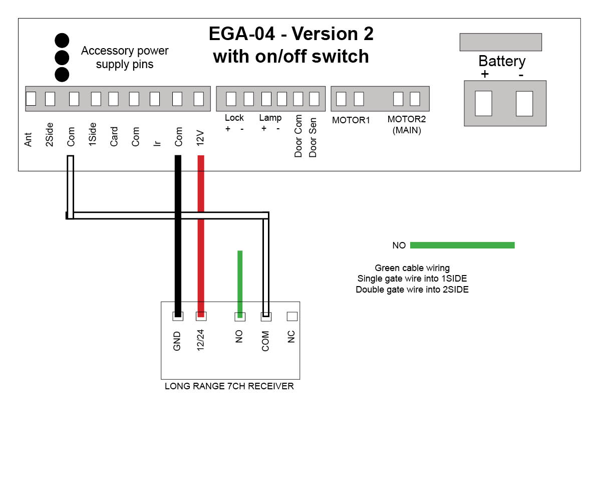
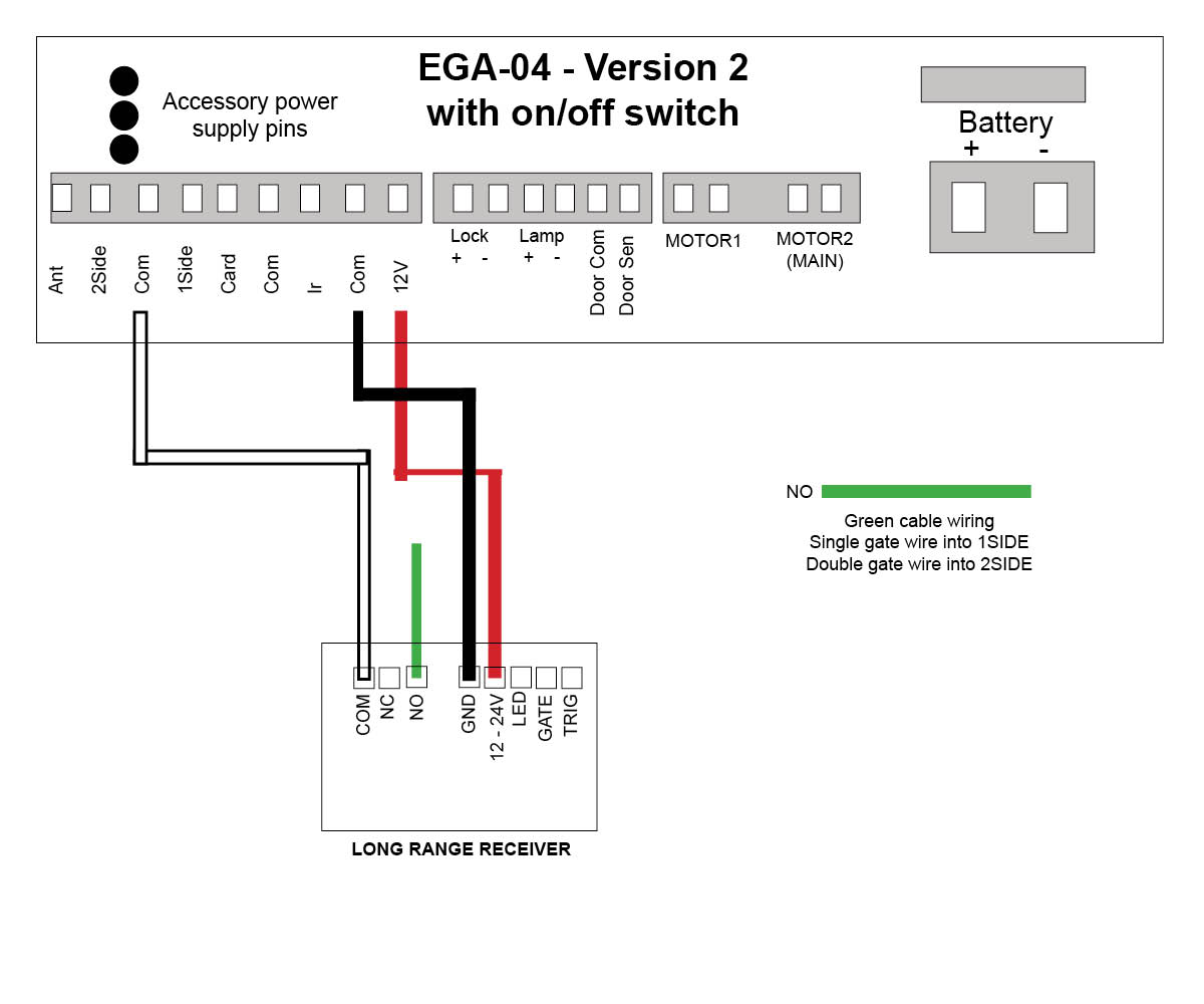
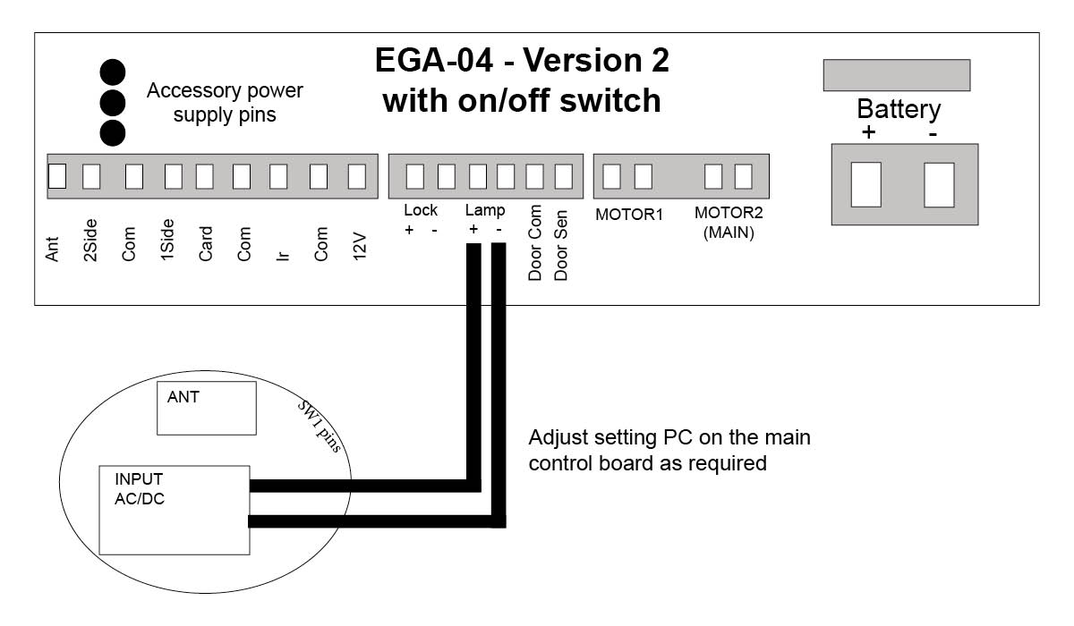
E8 Swing motor - EGA-04 version 2 board with on/off switch
Master Code = 999999 is the default factory master code
PIN = any four digits between 0000 & 9999 with the exception of 1234 which is reserved
User ID Number = any number between 1 & 2000
Important: if entering a number of different Pin Numbers into the keypad, it’s advisable to record the ‘User ID Number’ that matches to your ‘Pin Number’. If you need to delete a Pin Number in the furture you will need the User ID Number to remove it. If you fail to record these numbers then you will need to wipe all keypad numbers and start again.
We do recommend that you change the factory master code (999999) to a secure code which you must make note of. Failing to make note of your new master code will prevent you from being able to add or delete pin codes in the future. You would then be required to perform the 'reset'.
Please note, with all the instructions below we have used the factory Master Code of 999999. If you change this master code then you will need to use your new one instead.
How to enter a new pin code
Press *
Master Code (factory 999999) #
1
User ID number (pick from 1 up to 2000) #
PIN (0000 up to 9999) # * *
How to enter a new pin code - EXAMPLE
Press *
999999 #
1
100#
2468 # * * (2468 is now your new pin)
How to delete a pin code or swipe card/tag
Press *
Master Code (factory 999999) #
2
User ID number # * *
Note: if you have forgotten your User ID Number, then you will need to delete everything stored in the keypad
Delete all keypad pin codes
Press *
Master Code (factory 999999) #
2
0000 # *
Adding swipe card or tag
Press *
Master Code (factory 999999) #
1
User ID number (pick from 1 up to 2000) #
Tap card or tag # *
If adding multiple cards/tags, each one should have their own 'User ID' for ease of deleting if required
Setting the relay close time
Press *
Master Code (factory 999999) #
4
Select 1 sec # * *
Use this setting for double gates to both open.
How to change your master code
Your master code only requires to be changed if you require extra security on your keypad. You will need to take note of your master code as this will be used to add or delete pin codes in the future.
Press *
Master Code (999999) #
0
New Code # New Code #
New code can ber 6 to 8 digits
Reset to Factory Default
Disconnect power from the unit
Power the unit up, then press the # key
On hearing ‘didi’ release the # key, system is now back to factory settings
How to enter in a new pin code on your Keypad
Click on the motor you have below to see wiring diagrams:
E8 Swing motor - EGA-04 version 1 board
E8 Swing motor - EGA-04 version 2 board with on/off switch
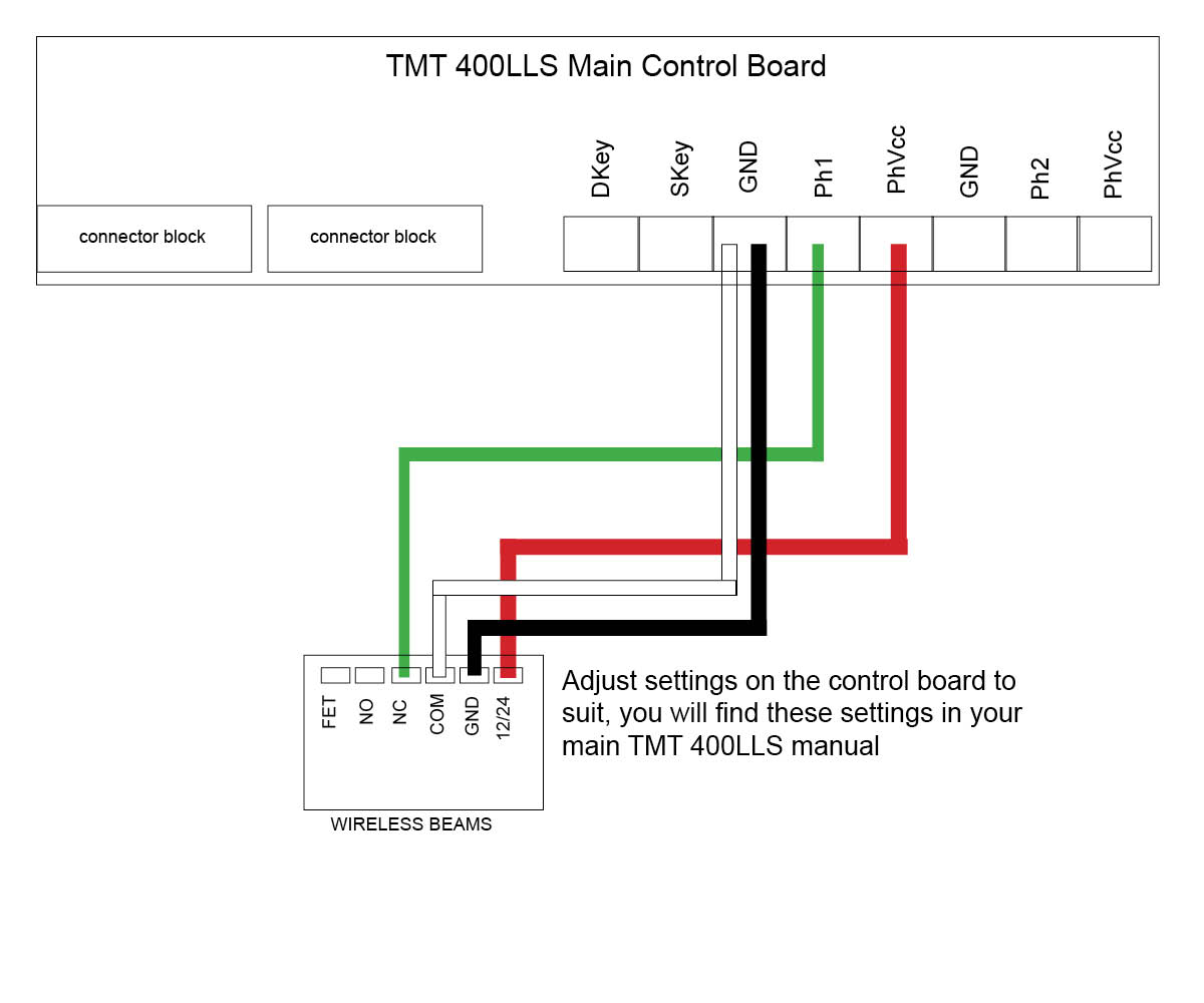
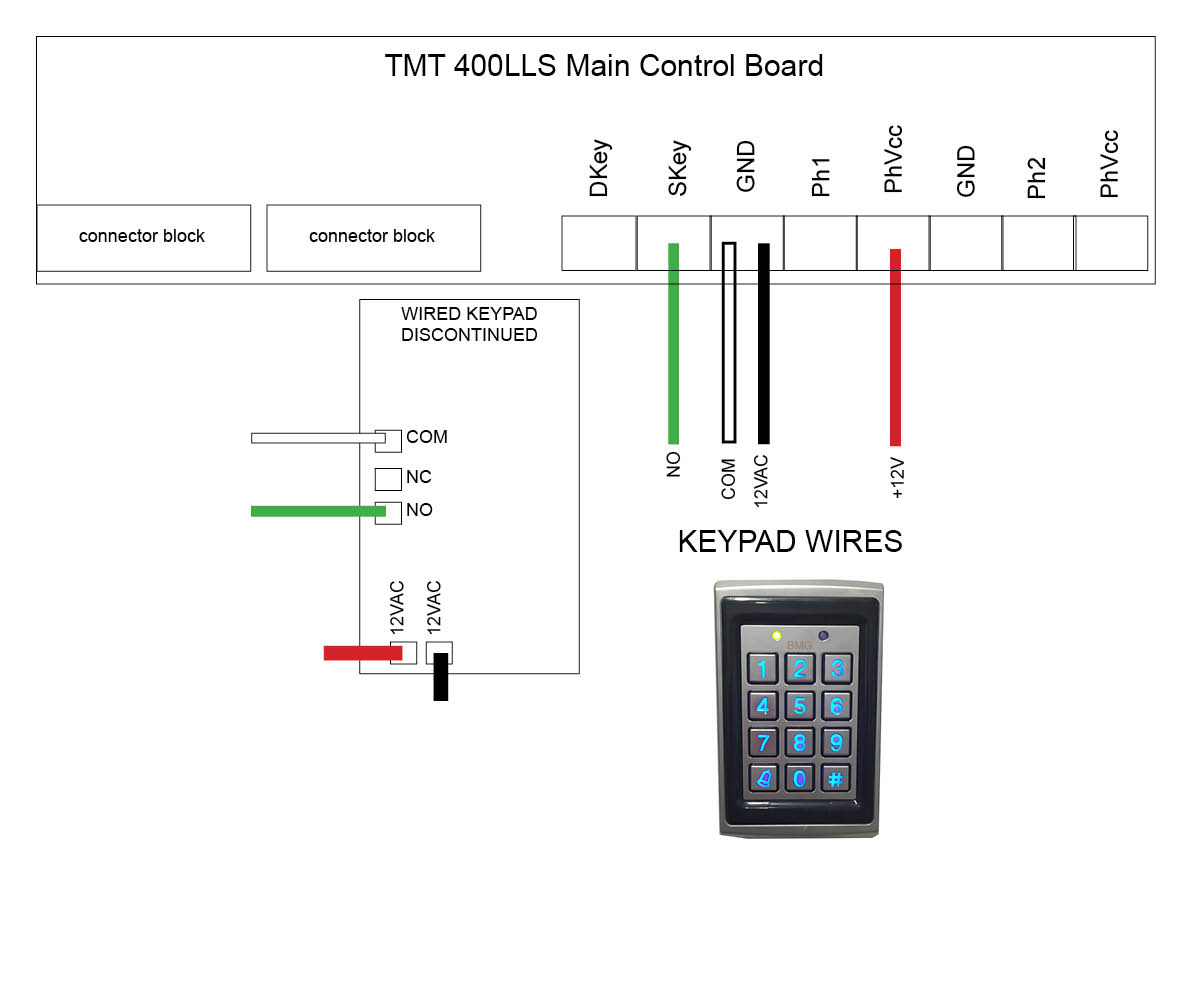
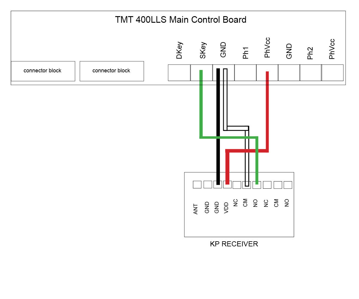
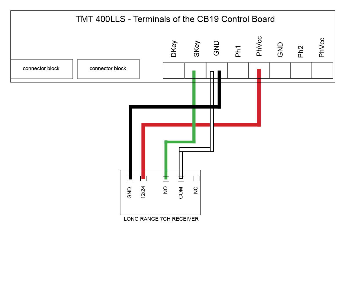
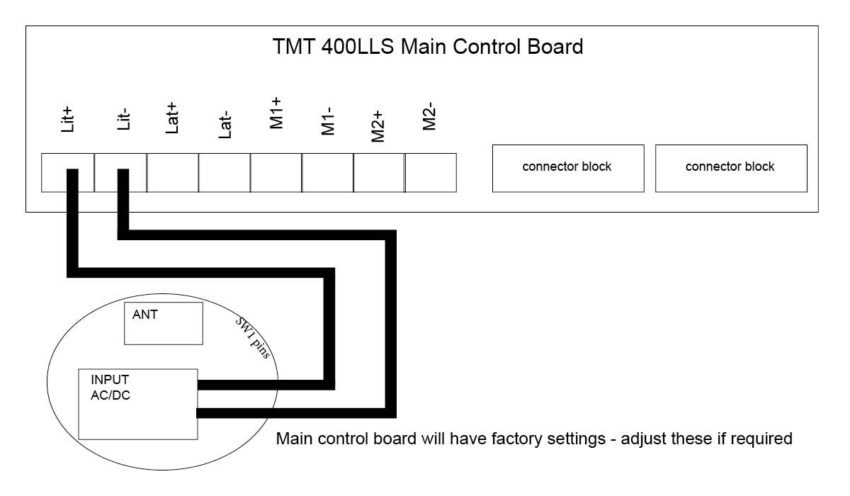
TMT 400LLS Swing motor
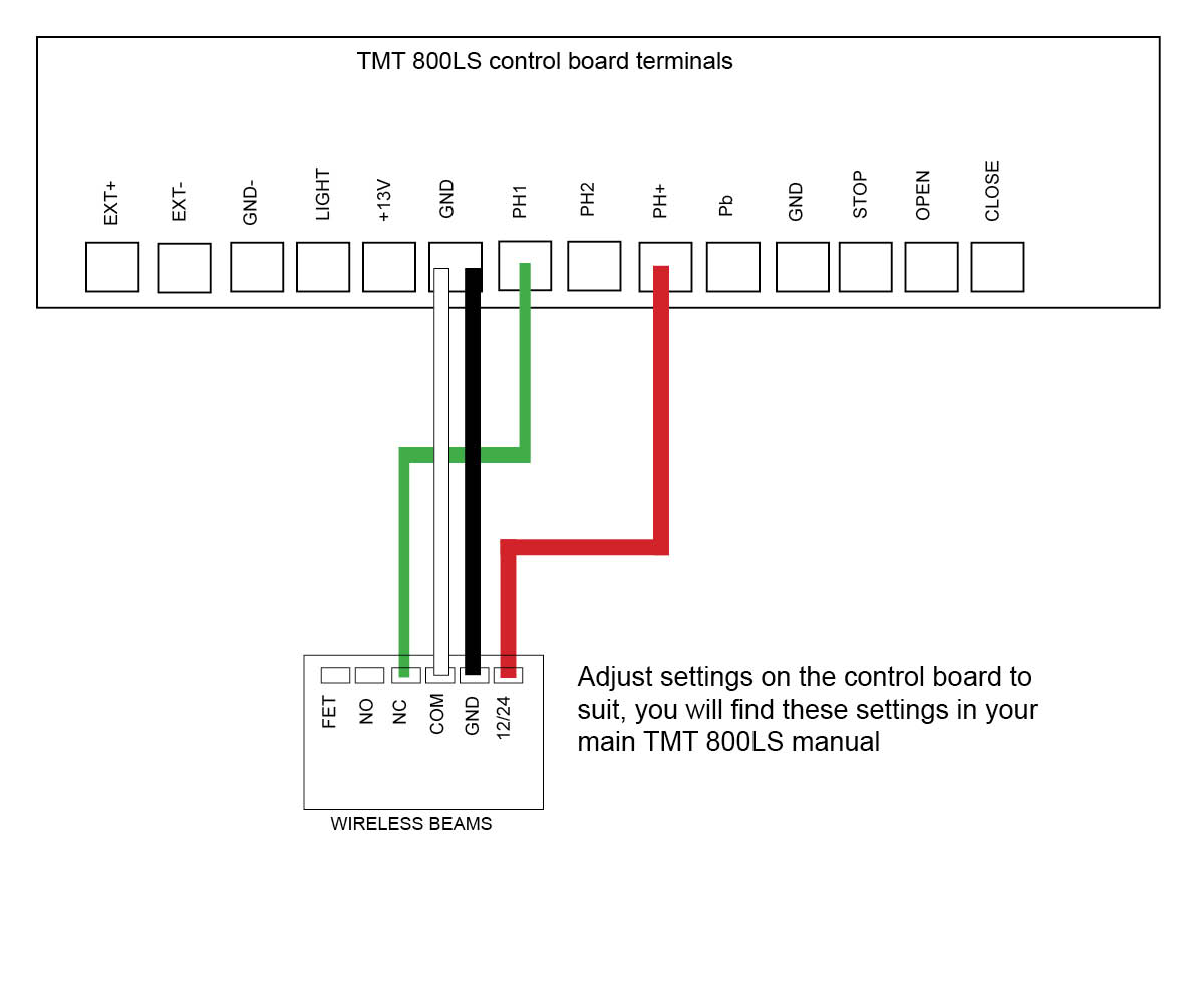
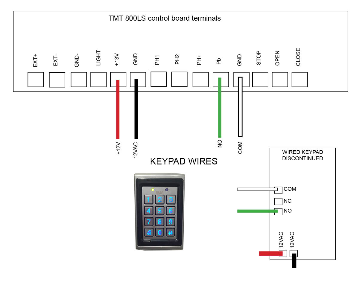
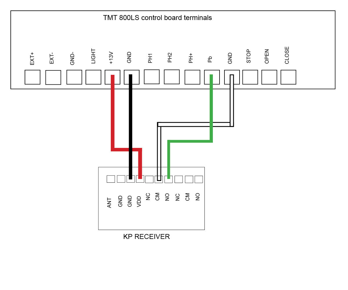
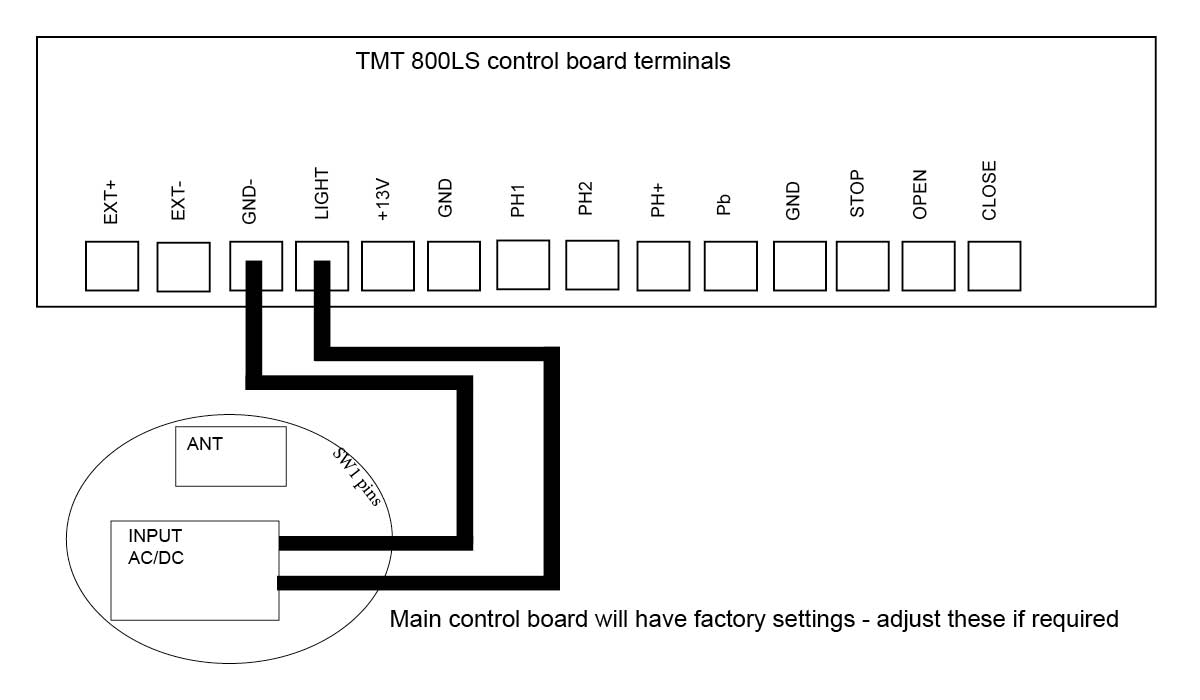
TMT 800LS Slide motor
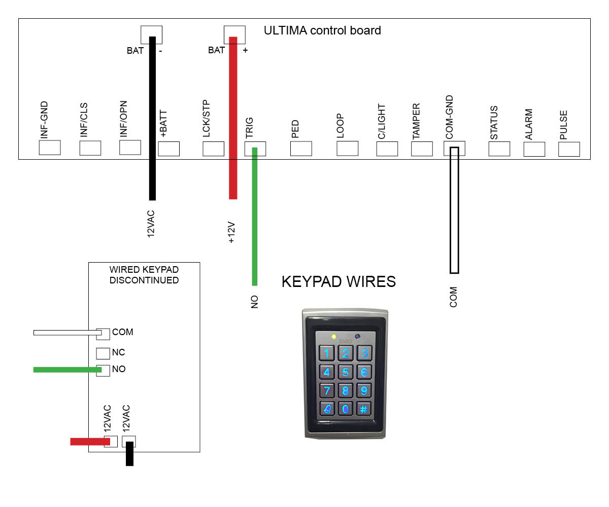
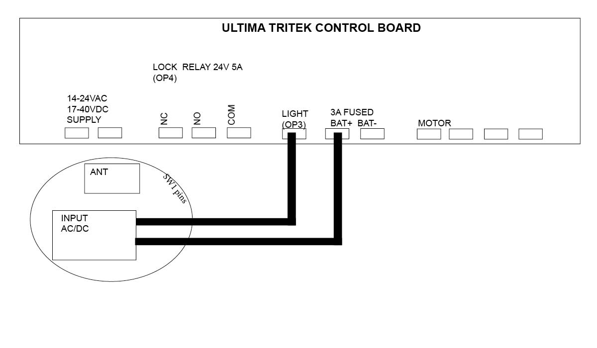
DACE Ultima Slide motor
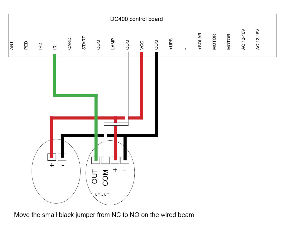
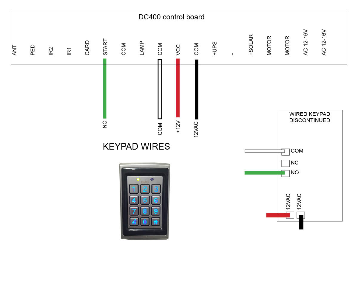
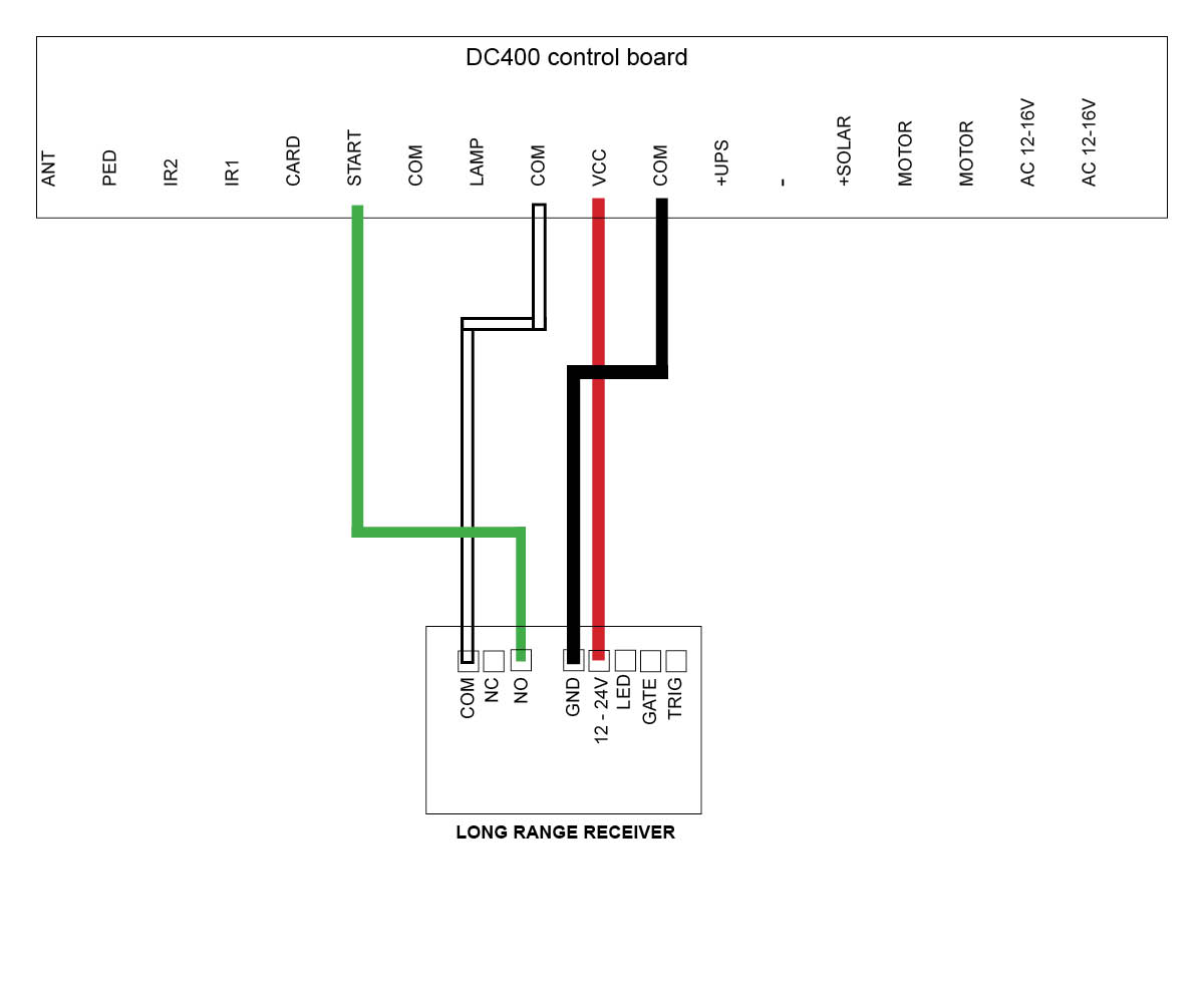
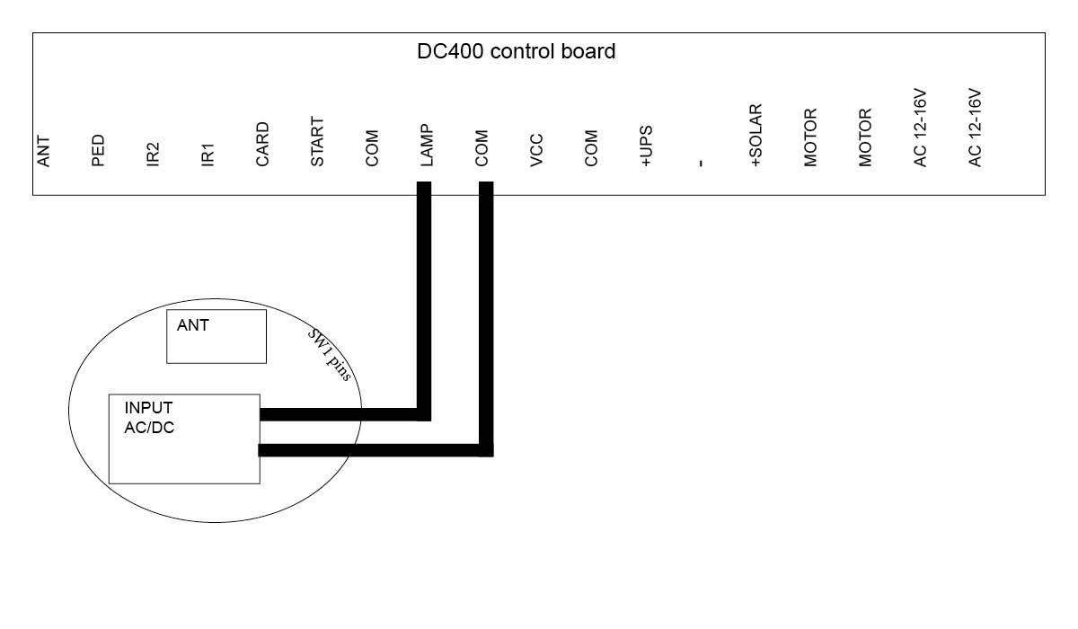
DC400 Slide motor (Discontinued)
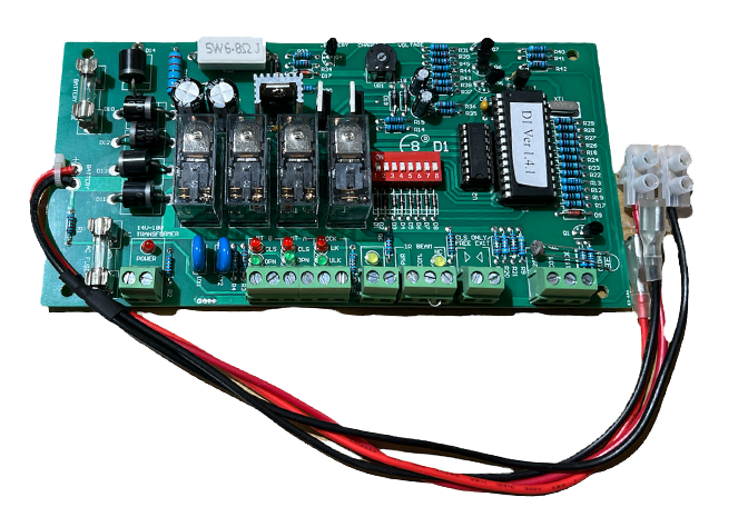
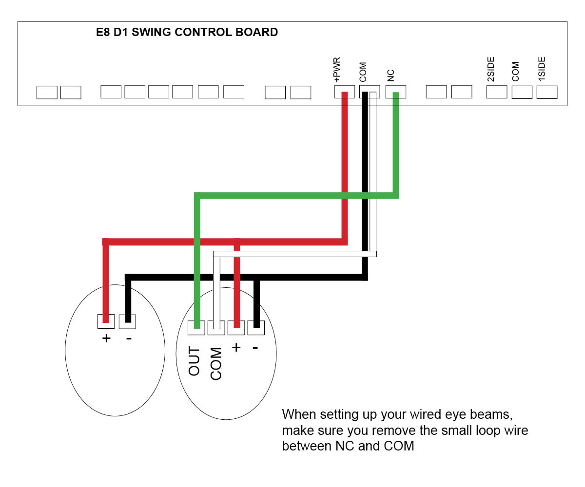
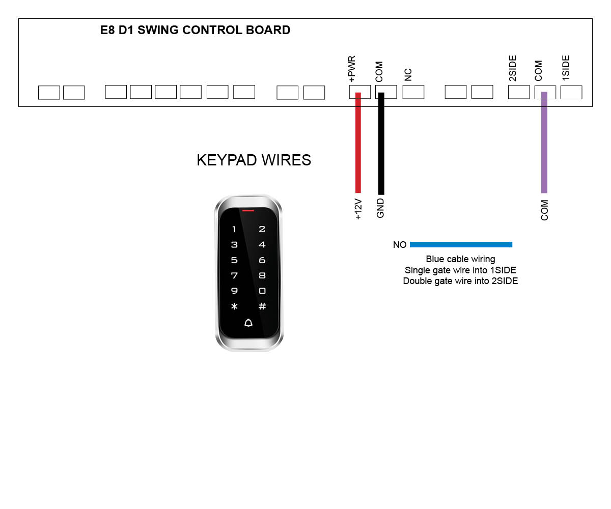
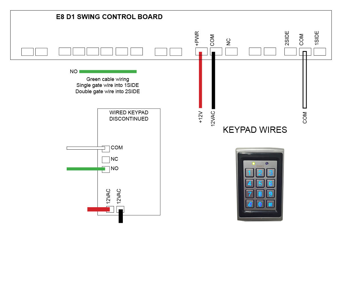
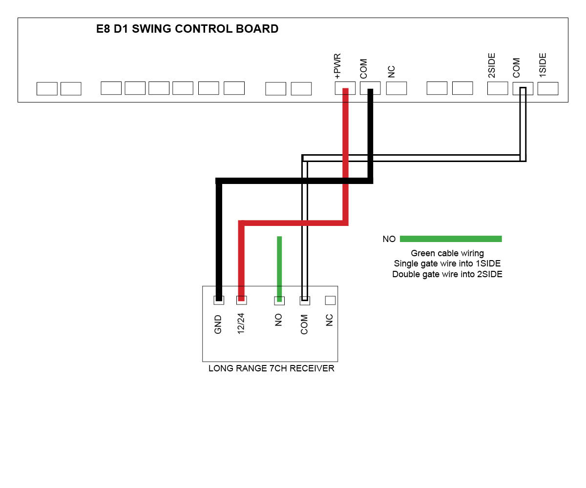
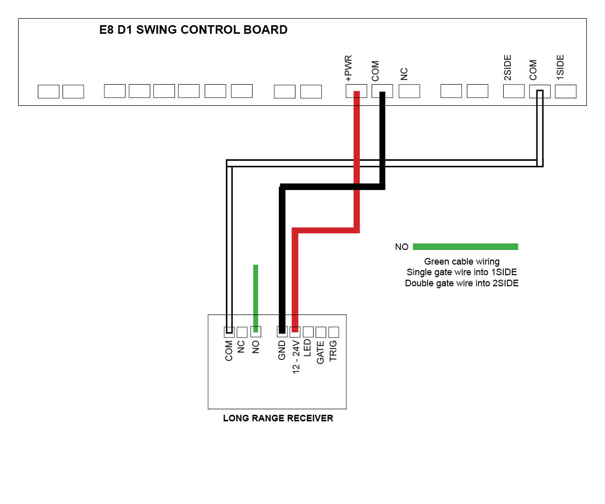
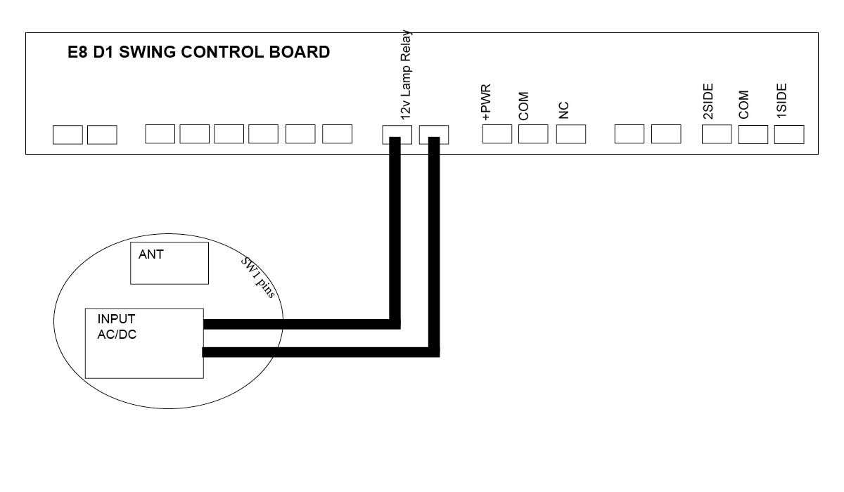
E8 Swing motor - D1 Board (Discontinued)
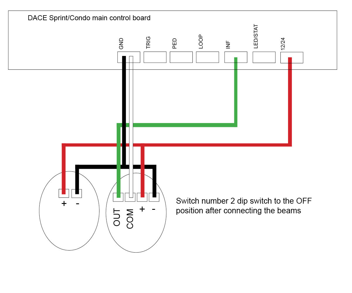
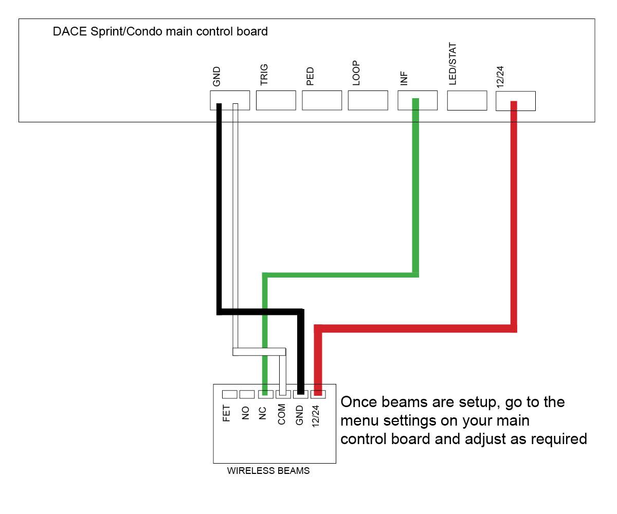
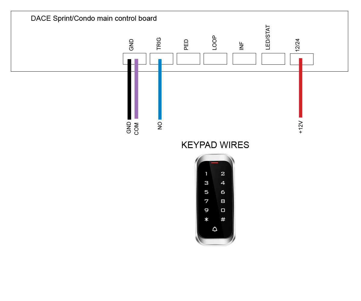
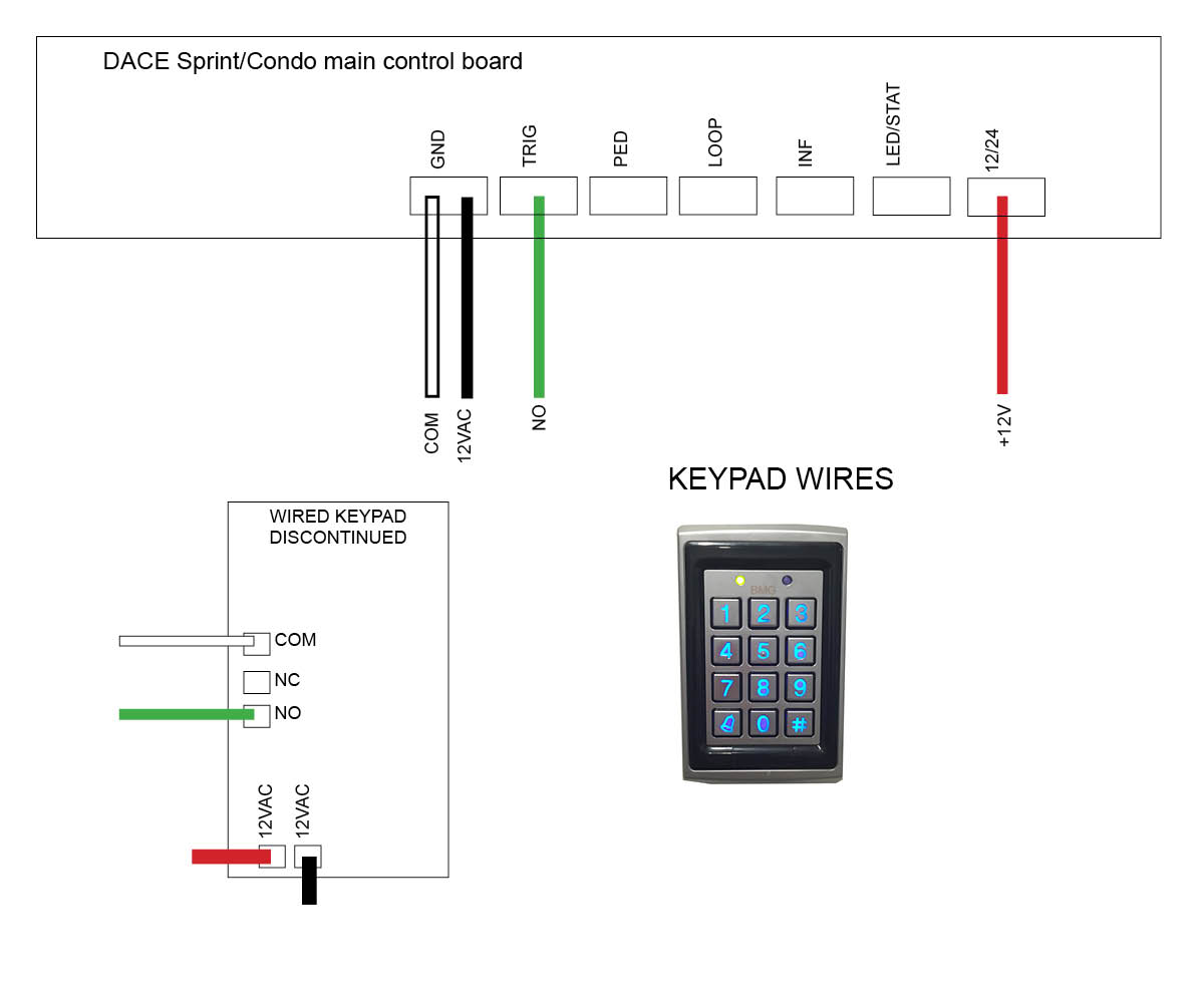
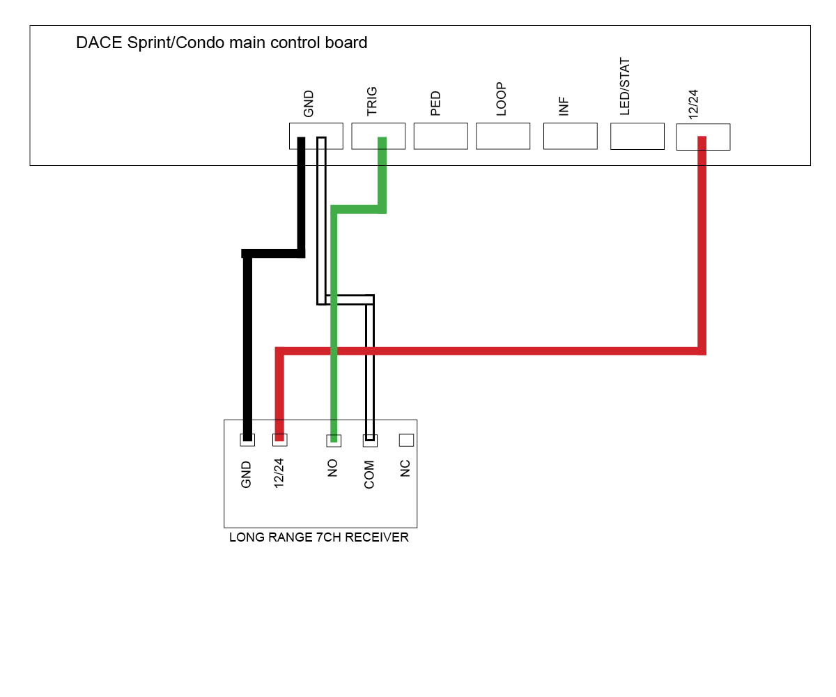
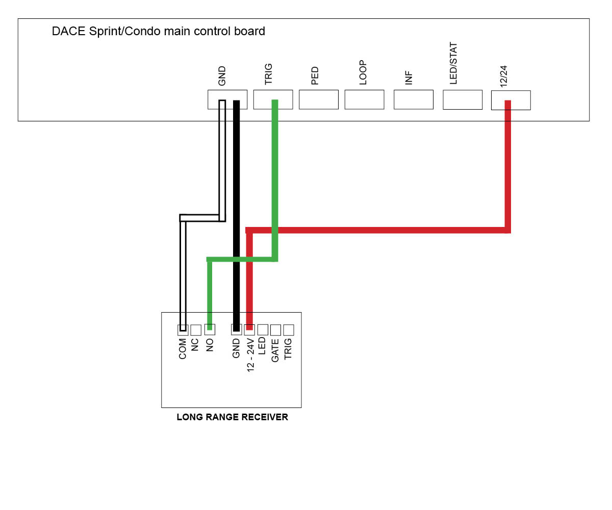
DACE Sprint/Condo Slide motor (Discontinued)
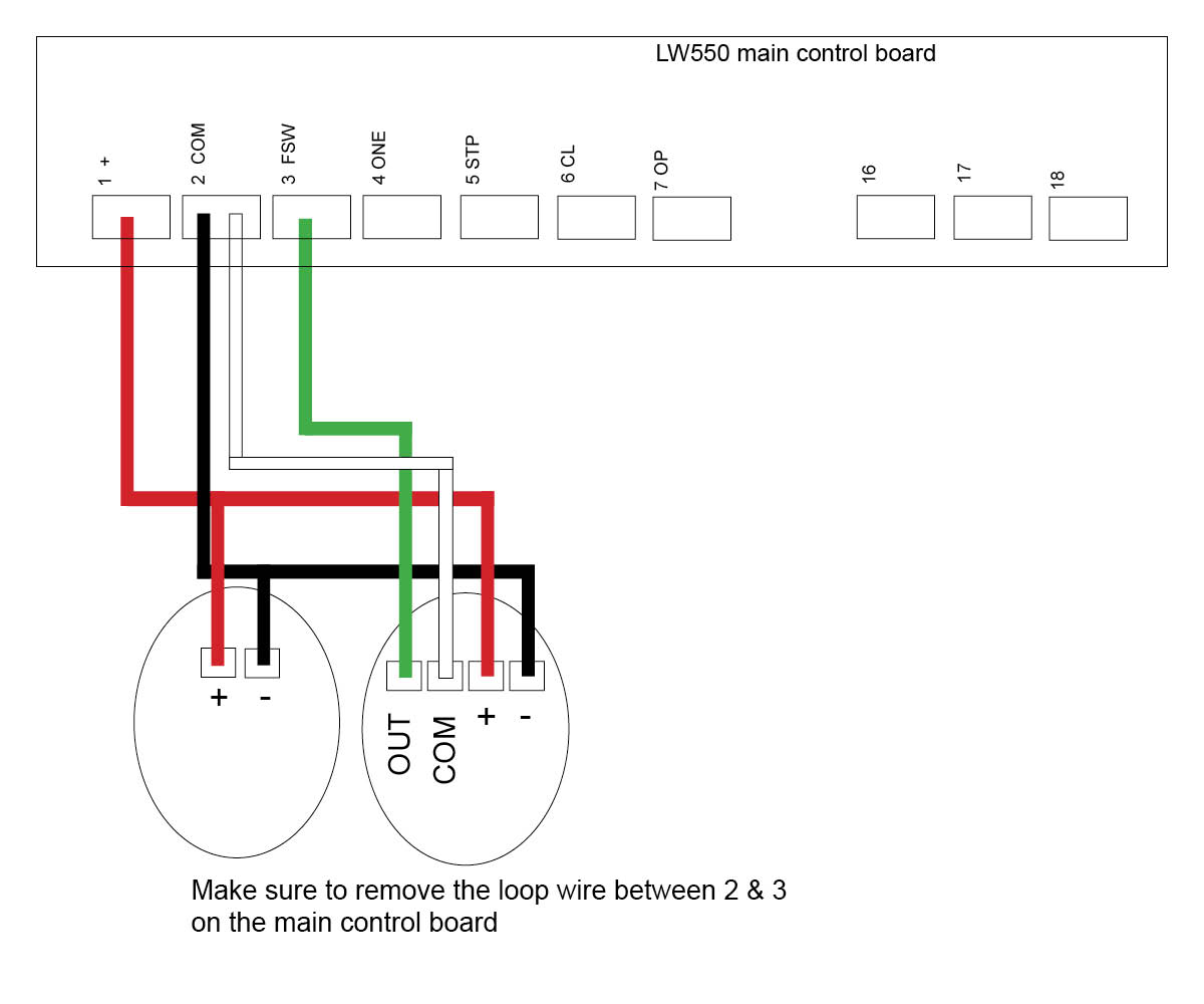
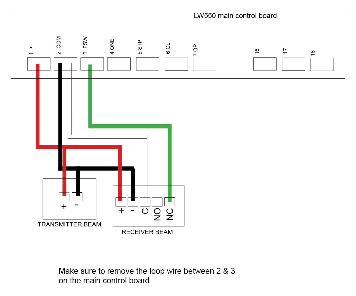
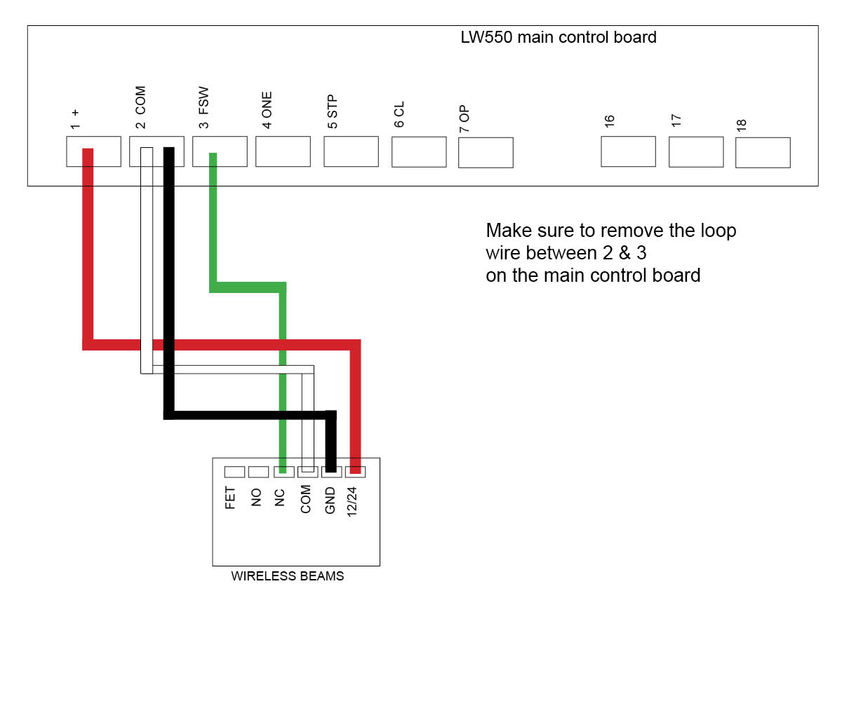
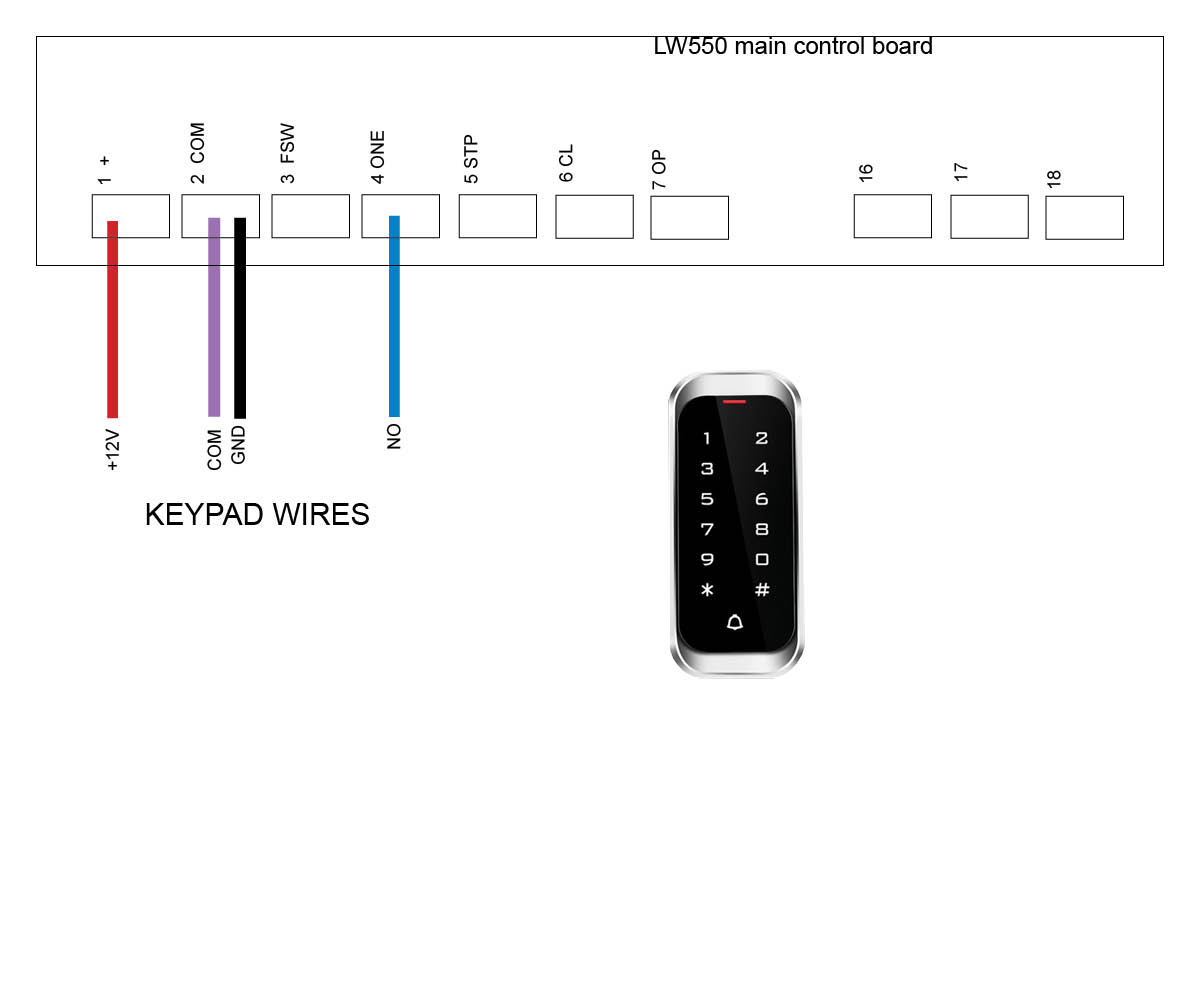
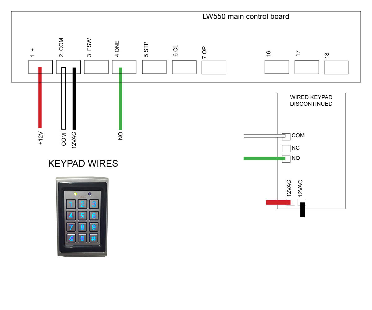
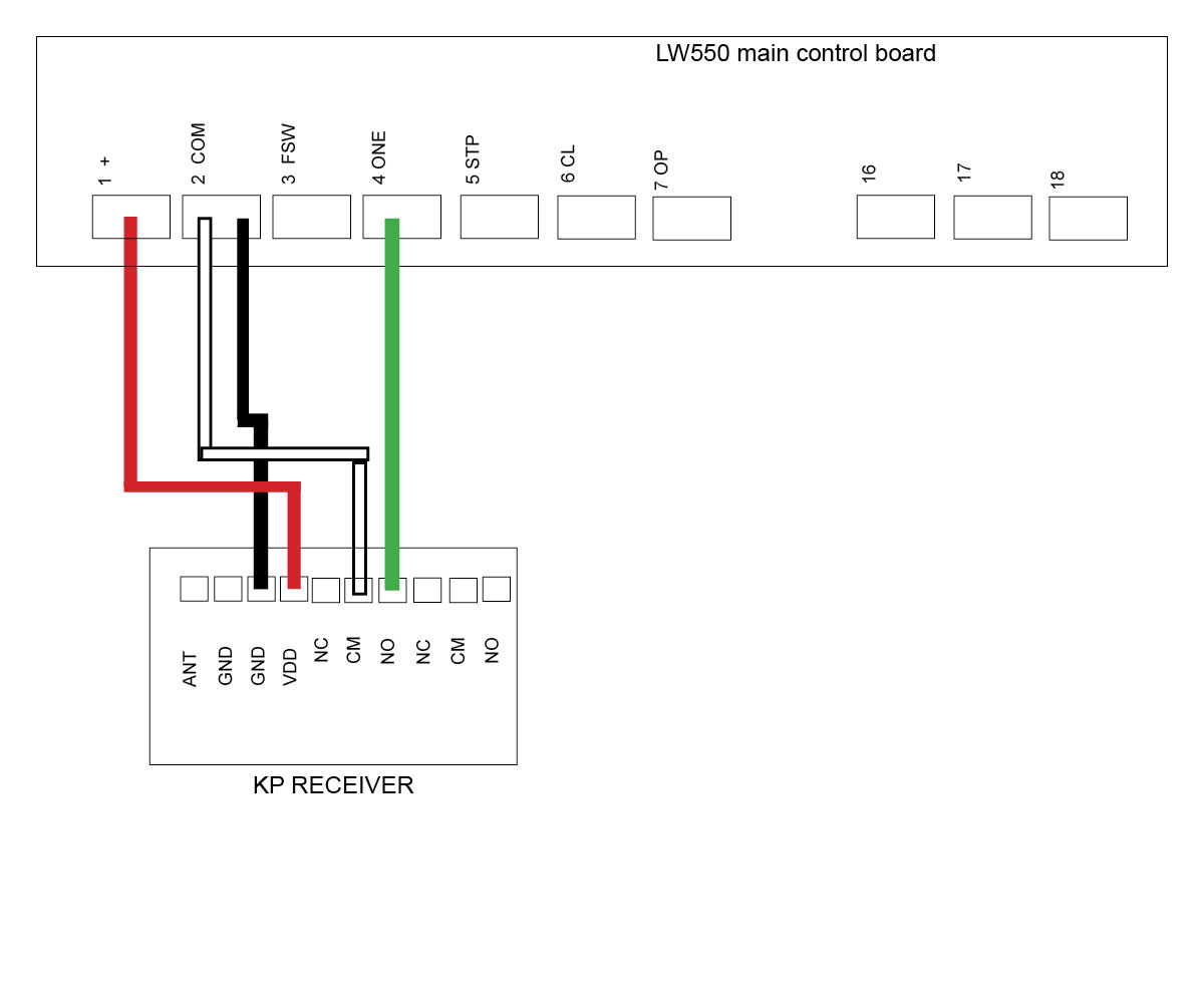
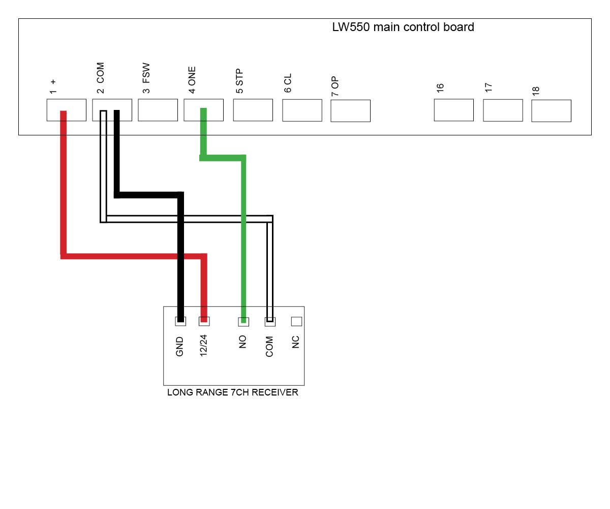
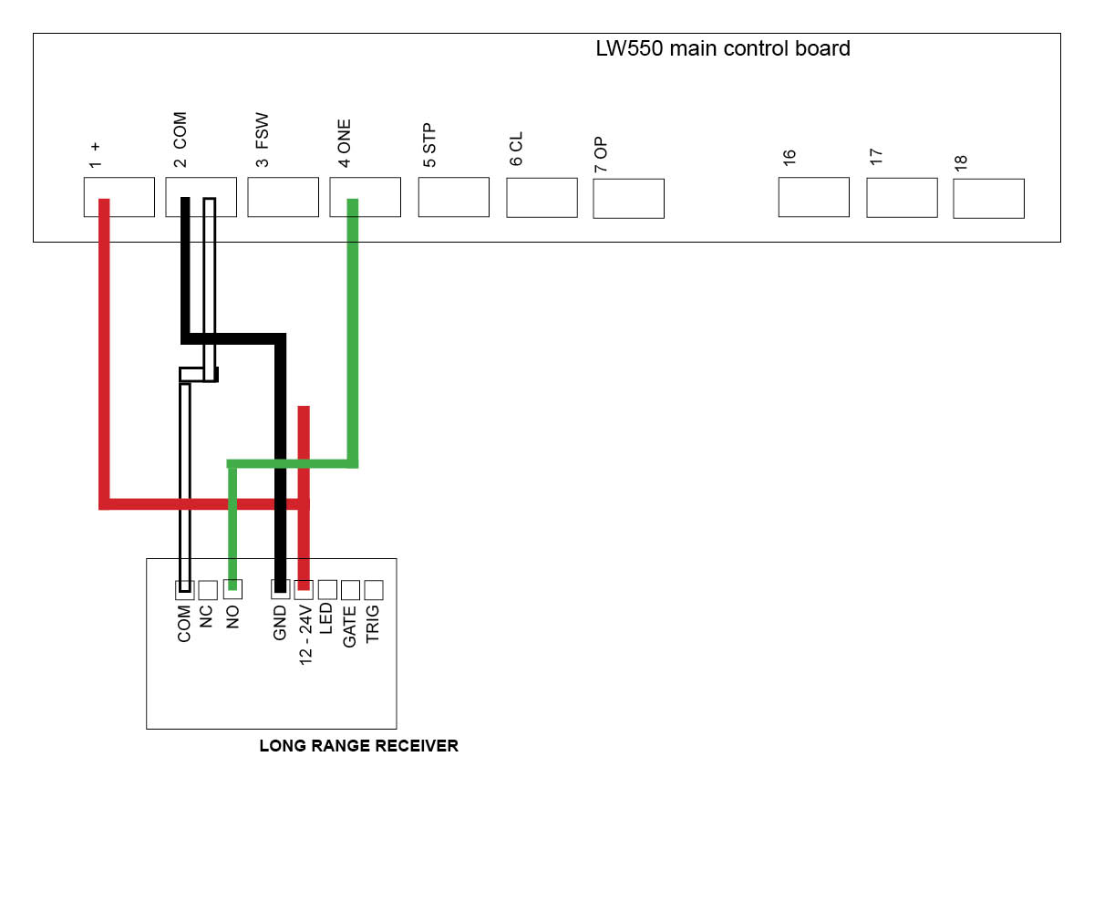
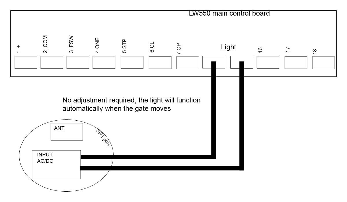
LW550 Slide motor (Discontinued)
Troubleshooting my keypad
This keypad is a sealed unit with approx 1mtr of cable.
Is the Keypad getting power? Test with a multimeter to check power is making it to the keypad wire coming out of the sealed unit. You should be getting at least 12volts DC at the wire and where the keypad is picking up power from the main unit. If not then try replacing the cable and see if it works now. If you are getting correct power try activating the cables from the keypad to see if the cabling is ok. To do this, remove the activating cables (COM and NO) from the keypad wire and tap the bare ends together, this should activate the gate telling you that your wire is good. If the gate works then you will require a new keypad. If the gate doesn't work, try replacing your cable.
After wiring your keypad, check that it’s operational by entering the 4 digit factory code 2580.
If you have double gates you will need to follow the setup noted below for 'Setting a delay time'.
Once gate/s are working with the factory code you can then move onto changing your master code and entering a new pin codes. You can enter over 100 pin codes.
Explaining the 3 digit user code and 4 digit pin code - When entering a new pin code you will be asked to enter in a 3 digit user code along with your 4 digit pin code. If having more than 1 pin code, the 3 digit user code must be different for each 4 digit pin code entered. The 3 digit user code is important to take note of as this is what you will need to remember if and when you need to remove your 4 digit pin code assigned to it. (eg. user code 147 & pin code 3698).
How to enter a new pin code
Press # (until the red light comes on)
Enter in your 4 digit master code (factory 1 2 3 4)
Press 7
Enter 3 digit user code
Enter 4 digit pin code
Press and hold #
Now test your pin code
Removing a pin code
Press # (until the red light comes on)
Enter in your 4 digit master code (factory 1 2 3 4)
Press 8
Enter 3 digit user code
Enter in your 4 digit master code (factory 1 2 3 4)
Press #
Back Light
When pressing #, wait till red LED light comes on
Light off Press - # (master code) 6 2800
Light on Press - # (master code) 6 2801
Light on when pincode pressed only -
press # (master code) 6 2802
Set a delay time
This may be required for double gates if they are not opening together
Press # (until the red light comes on)
Enter in your 4 digit master code (factory 1 2 3 4)
Press 6 000 1
How to change your master code
Your master code only requires to be changed if you require extra security on your keypad. You will need to take note of your master code as this will be used to add or delete pin codes in the future. If you forget your master code then you will need to follow the 'Reset to factory default' and start again.
Press # (until the red light comes on)
Enter in your 4 digit master code 1 2 3 4
Press 3
Enter your new 4 digit master code
Reset to Factory Default
Press # (until the red light comes on)
Enter in your 4 digit master code (factory 1 2 3 4)
Press 0 (both red lights flash)
Enter in your 4 digit master code (factory 1 2 3 4)
This function comes in handy when you don’t know the 3 digit user code to “remove a pin code”, however using the factory reset will wipe all user codes and pin codes from the keypad and sets it back to 2580. When you enter your new pin code it will wipe the factory setting 2580
How to enter in a new pin code on your Keypad
Click on the motor you have below to see wiring diagrams:
E8 Swing motor - EGA-04 version 1 board
E8 Swing motor - EGA-04 version 2 board with on/off switch
TMT 400LLS Swing motor
TMT 800LS Slide motor
DACE Ultima Slide motor
DC400 Slide motor (Discontinued)
E8 Swing motor - D1 Board (Discontinued)
DACE Sprint/Condo Slide motor (Discontinued)
LW550 Slide motor (Discontinued)
Troubleshooting my keypad
Are there signs of insect infestation past or present inside the unit? check for signs of insects past or present, there will usually be dirt, faeces, trails etc inside the unit or on the control board. If there are notable signs of infestation at some point then you will need a new keypad.
Are there signs of corrosion? Check the control board and cable terminals for signs of corrosion, if there is only slight corrosion, try cleaning it up. Otherwise you will require a new keypad.
Is the Keypad getting power? Test with a multimeter to check power is making it to the keypad board. You should be getting at least 12volts DC at the keypad and where the keypad is picking up power from the main unit. If not then try replacing the cable and see if it works now. If you are getting correct power try activating the cables from the keypad to see if the cabling is ok. To do this, remove the activating cables (COM and NO) from the keypad and tap the bare ends together, this should activate the gate telling you that your wire is good. If the gate works then you will require a new keypad. If the gate doesn't work, try replacing your cable.
1. Press P1 on the receiver board (red LED will go solid)
2. Press the device you are trying to tune and hold for 3 seconds (red LED will flash to say device and receiver are paired)
Deleting your device from the KP Receiver
Press P2 on the receiver board for 8 seconds (red LED will go solid, your device and KP receiver are now unpaired)
Click on the motor you have below to see wiring diagrams:
E8 Swing motor - EGA-04 version 1 board
E8 Swing motor - EGA-04 version 2 board with on/off switch
TMT 400LLS Swing motor
TMT 800LS Slide motor
DACE Ultima Slide motor
DC400 Slide motor (Discontinued)
E8 Swing motor - D1 Board (Discontinued)
DACE Sprint/Condo Slide motor (Discontinued)
LW550 Slide motor (Discontinued)
Tuning a Remote to the KP Receiver
Tuning the Wireless Button to the KP Receiver
Tuning the Wireless Keypad to the KP Receiver
Troubleshooting the KP Receiver
This troubleshooting assumes that your keypad, remotes etc.. are in working order. If you have not done so already, troubleshoot these devices first!
Are there signs of insect infestation past or present inside the unit? Open up the receiver box and check there are no ants or insects past or present. If there is evidence of this then you will require a new receiver.
Check that the receiver is receiving a signal from the tuned device (keypad, push button or remote) by listening for a click sound coming from the receiver when the device is pressed. If you hear a click sound then you know you're getting power and the device is still tuned in. If you don't hear the click try re tuning the device to the receiver. see videos above for tuning help.
Is the receiver getting power and or the correct voltage required? Test with a multimeter to check power is making it to the receiver. You should be getting at least 12volts. If you don't get the correct voltage try replacing the cables. If the unit still doesn't work after new cable then you will need a new receiver.
If you are getting correct power to the receiver try removing the NO and COM cables from the receiver and tapping the bare cables together which should activate the gate. If the gate doesn't activate, replace cable.
If the gate activates when tapping the COM and NO cables together and you have the correct volts at the receiver, try re wiring the receiver and see if the unit works now. If no, then you will require a new receiver.
With the power connected to the receiver, place the black jumper link over the RELAY pins (if this is not already set).
Press and hold the remote button to be programmed to the receiver. Wait for the green light on the receiver to flash quickly.
While pressing the remote button, place the 2nd black jumper link over the REMOTE pins for 2 seconds (only) and then remove the black jumper link. Now test that the remote works.
When finished, make sure to place the 2nd black jumper back on 1 pin only.
Erasing a single remote button from receiver
You will use the button that holds the position in the receiver immediately before the one that is to be erased!!
With the power connected to the receiver, press and hold the button on the remote that was programmed to the receiver before the button that is to be erased.
Place a link over the ERASE pins. The LED will flash twice and then remain solid.
Release the remote button
Remove the link.
The remote button is now erased from the receiver.
Erasing all remotes
With the power connected to the receiver, place a link over the ERASE pins.
The LED will flash ten times and then remain on solid.
Remove the link.
The remote buttons have now been erased from the receiver.
MANUFACTURERS RECOMMENDATIONS AND COMMENTS
For optimum range it is advisable to place the receiver a minimum of 2
metres vertically away from the gate motor e.g. top of gate posts.
When placing the receiver outside of the control box or motor housing it is
important to use a weatherproof box with all entry points sealed. The standard
receiver housing is only splash proof and not suitable for outdoor applications. **
Make sure there are no exposed wires outside the receiver.
Placing the receiver inside the motor housing will reduce the range of the
receiver when the motor is in operation.
Range may be affected by signals transmitted from another source.
When coding remotes for use in a complex it is recommended that all
remotes be physically numbered and a record be kept.
* All dependent on line of sight to the gate and interference which may
reduce expected range. DO NOT ALTER THE ANTENNA IN ANY WAY (TUNED
LENGTH ANTENNA)
** Warranty will void if the receiver housing has been placed outside and not in a
recommended weatherproof box.
Tuning a wireless push button
Tuning a remote
Tuning a wireless keypad
Click on the motor you have below to see the wiring diagram:
E8 Swing motor - EGA-04 version 1 board
E8 Swing motor - EGA-04 version 2 board with on/off switch
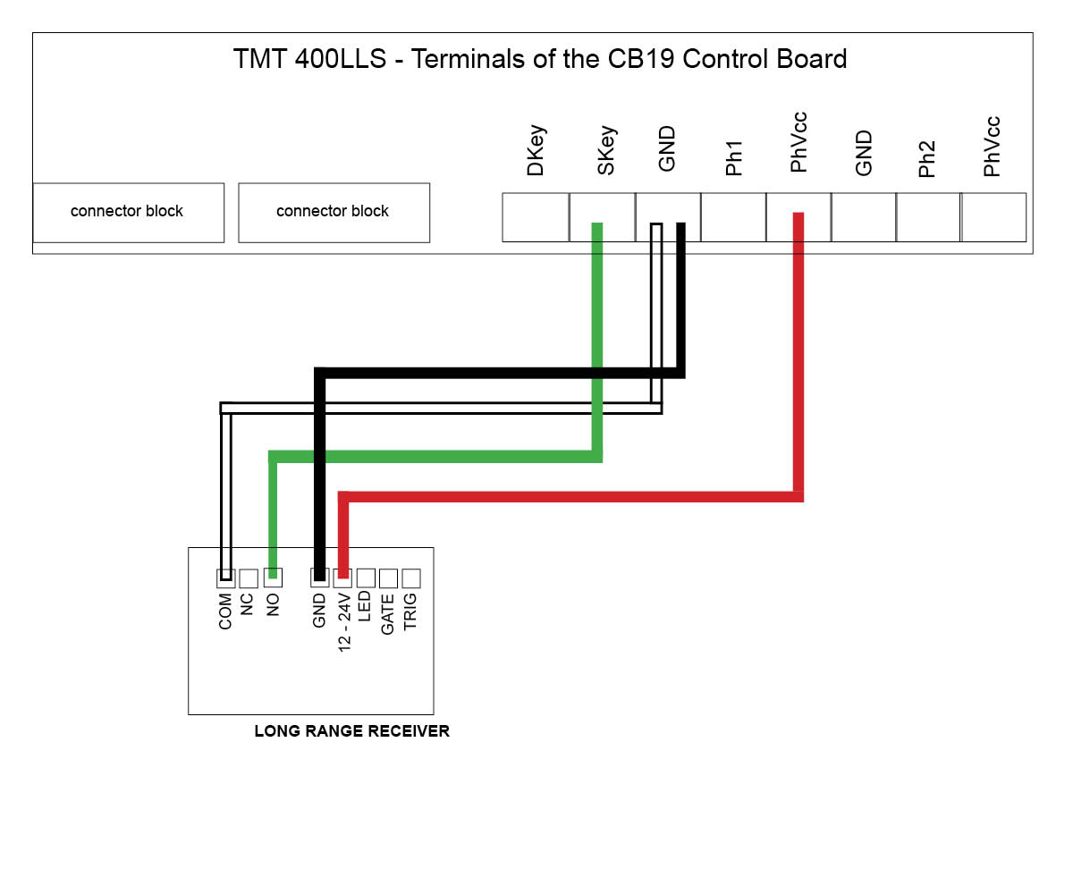
TMT 400LLS Swing motor
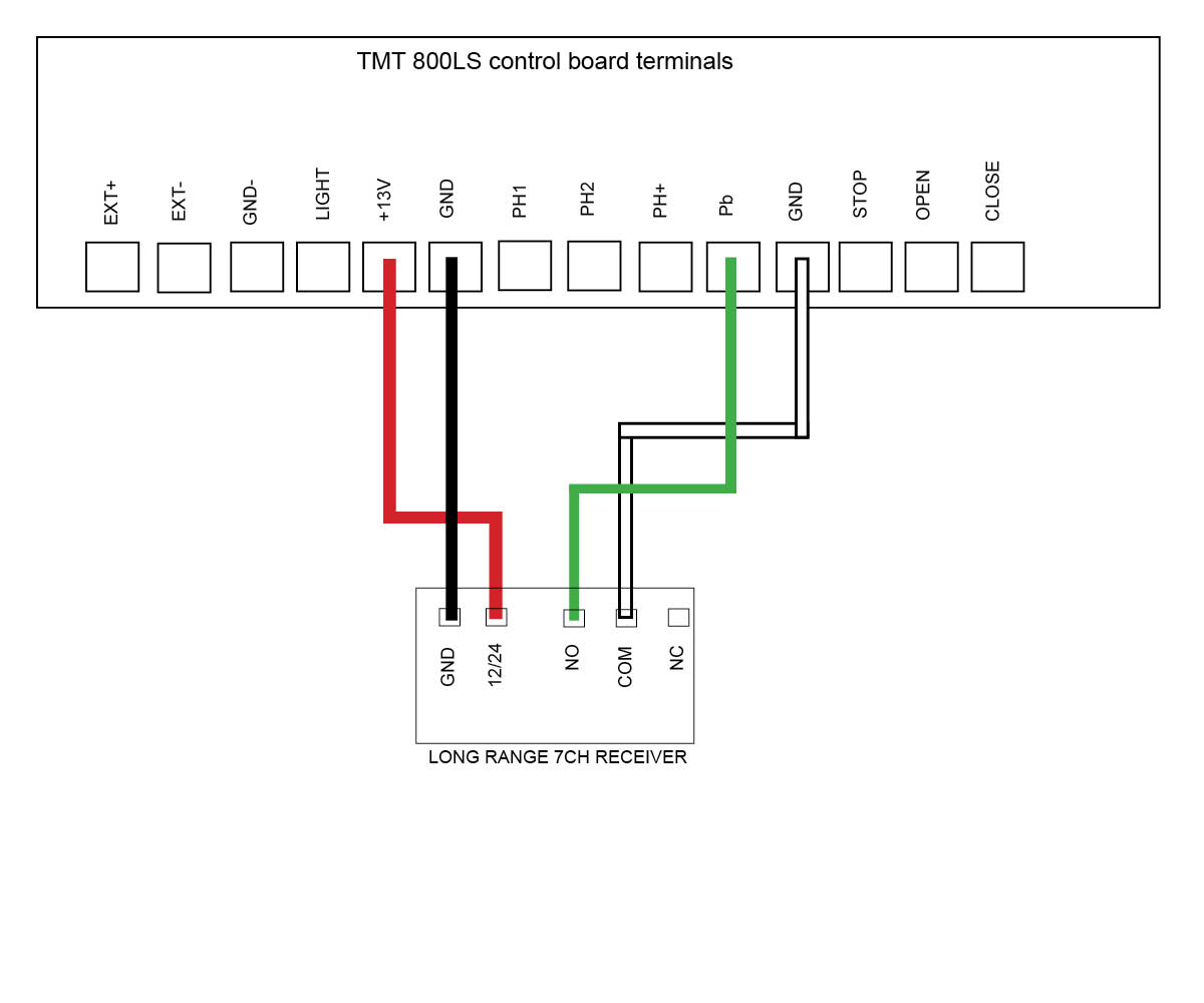
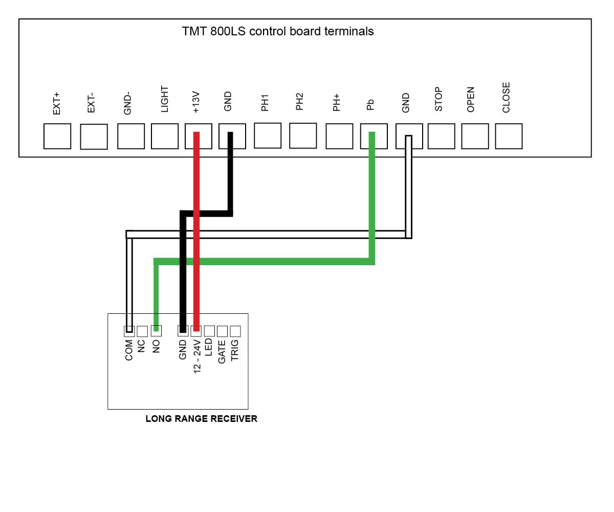
TMT 800LS Slide motor
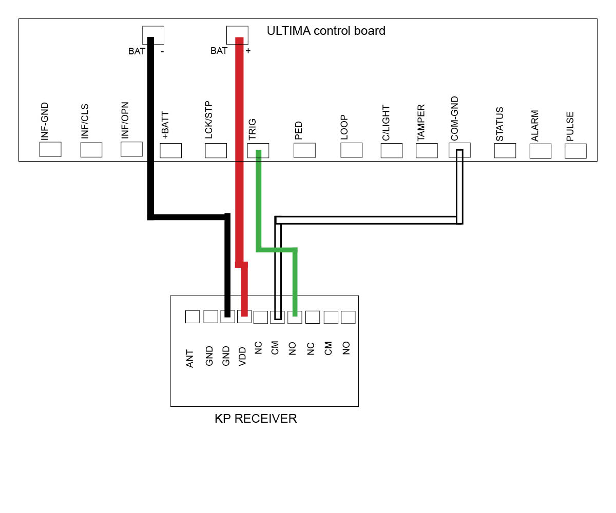
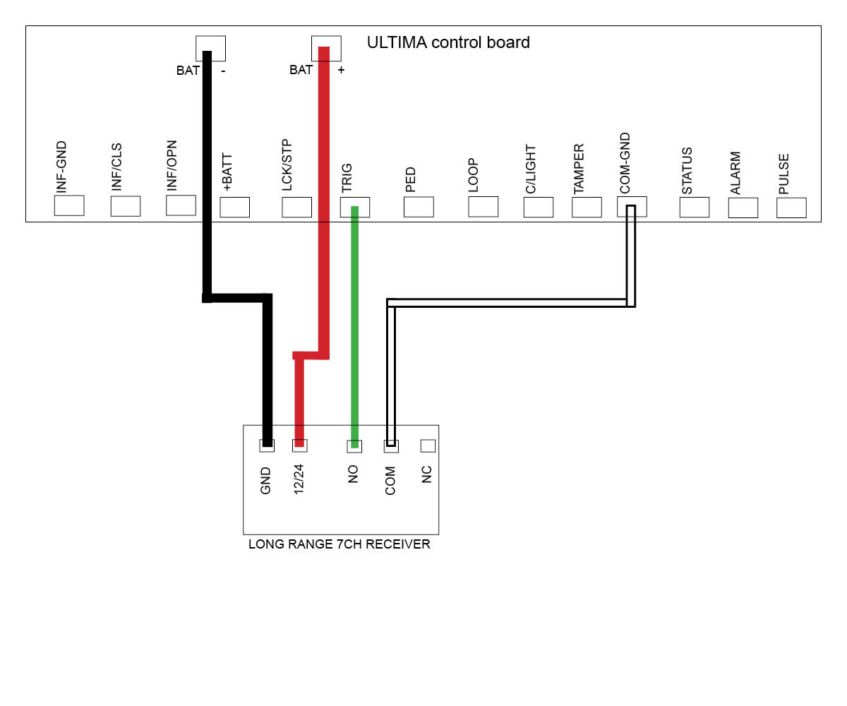
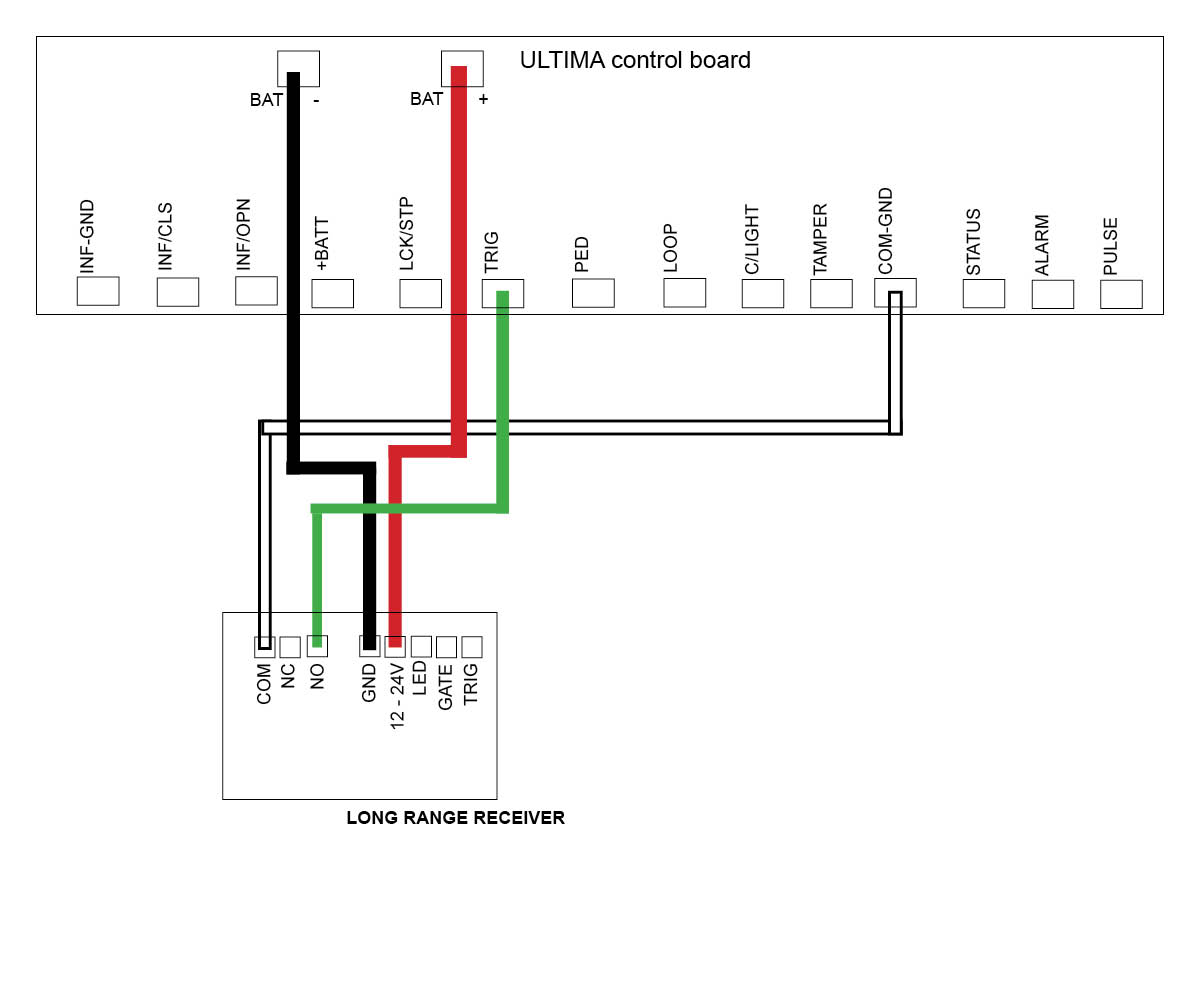
DACE Ultima Slide motor
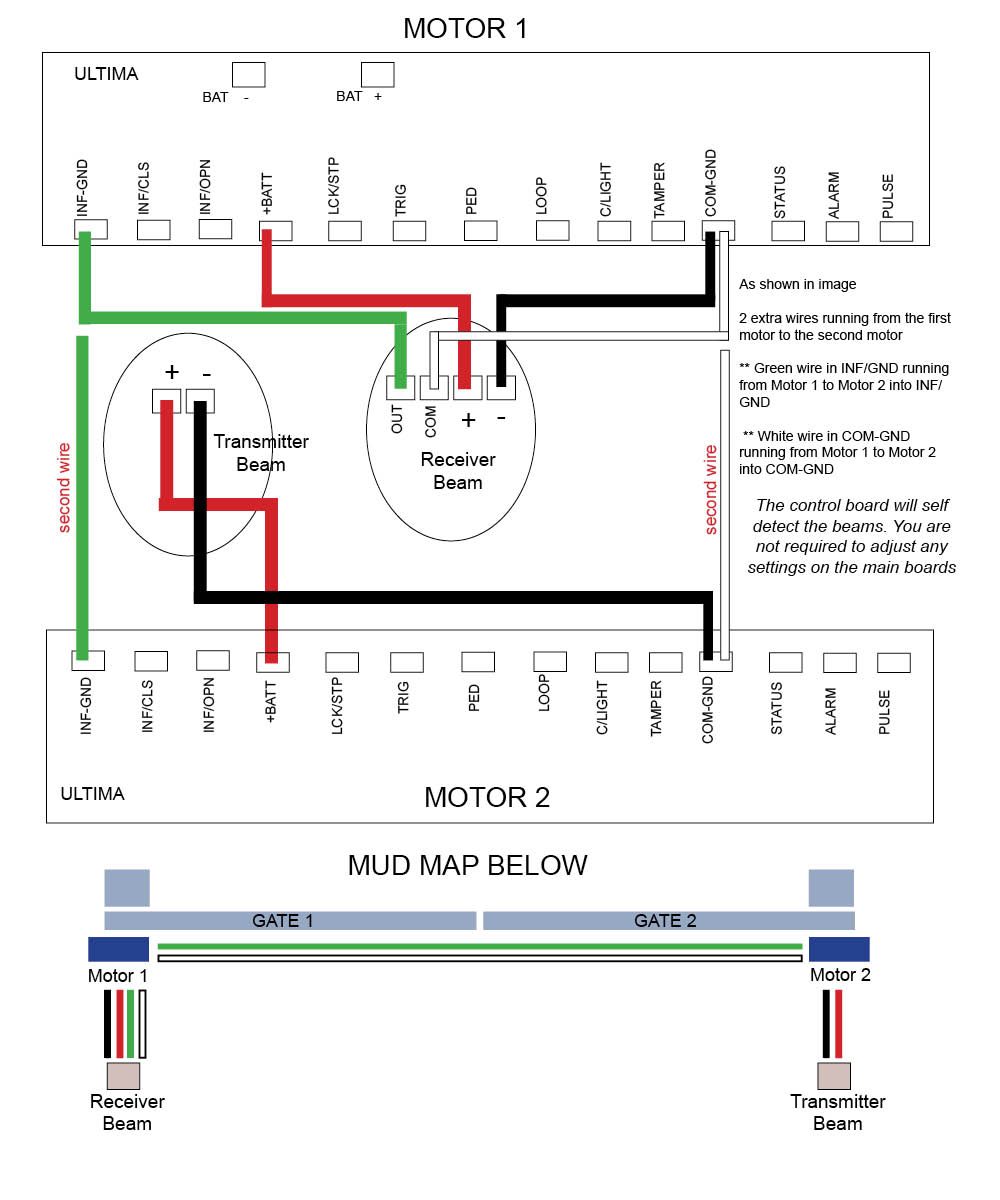
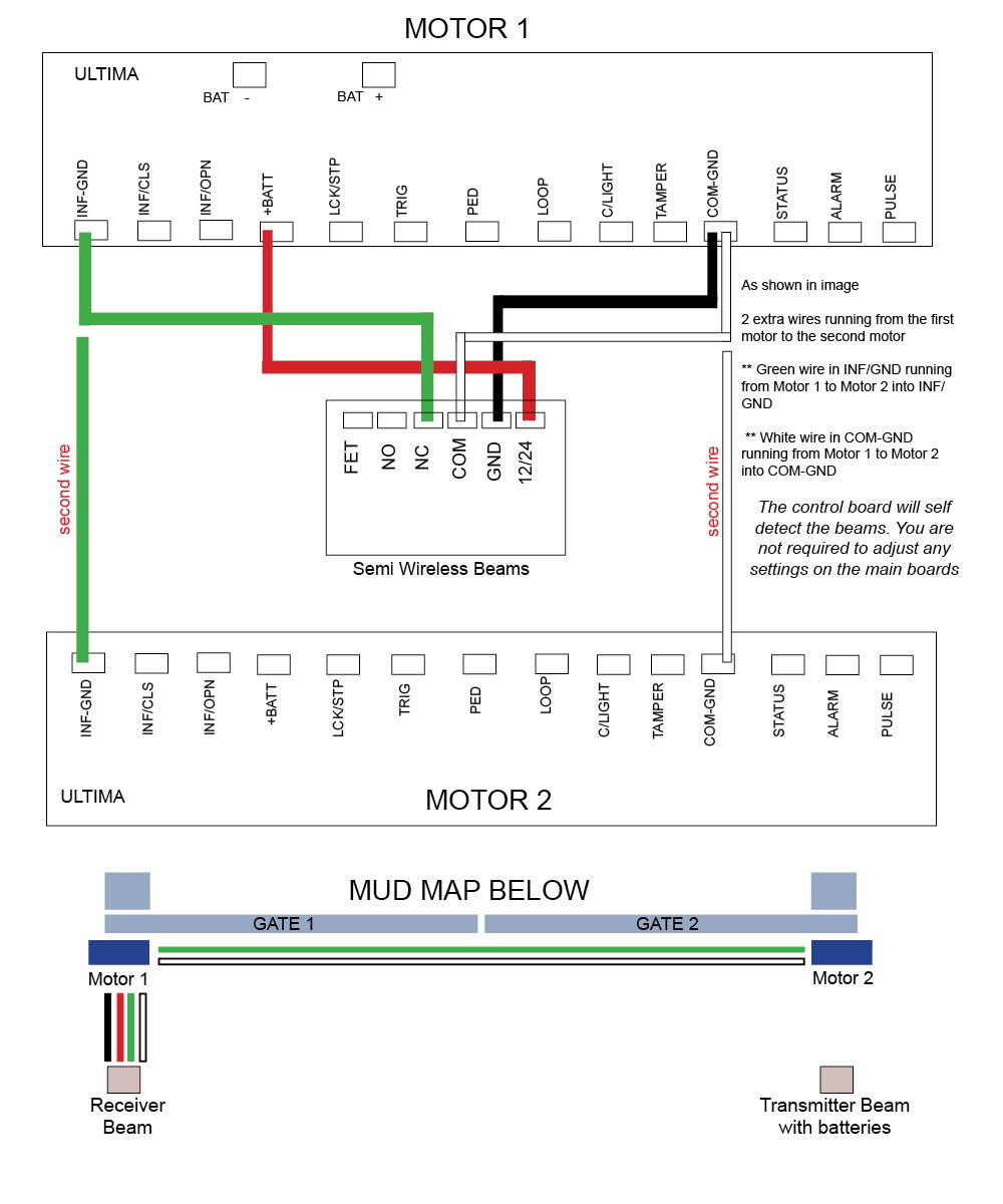
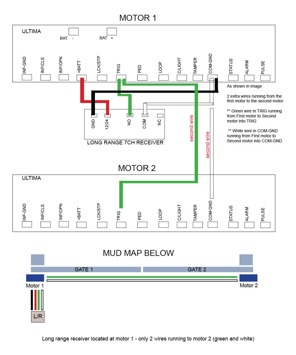
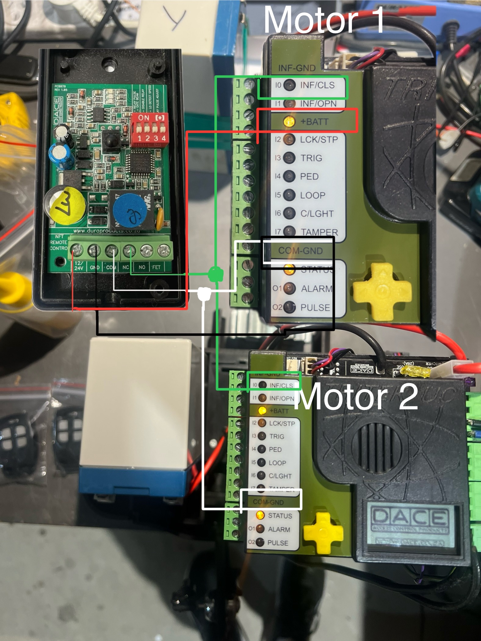
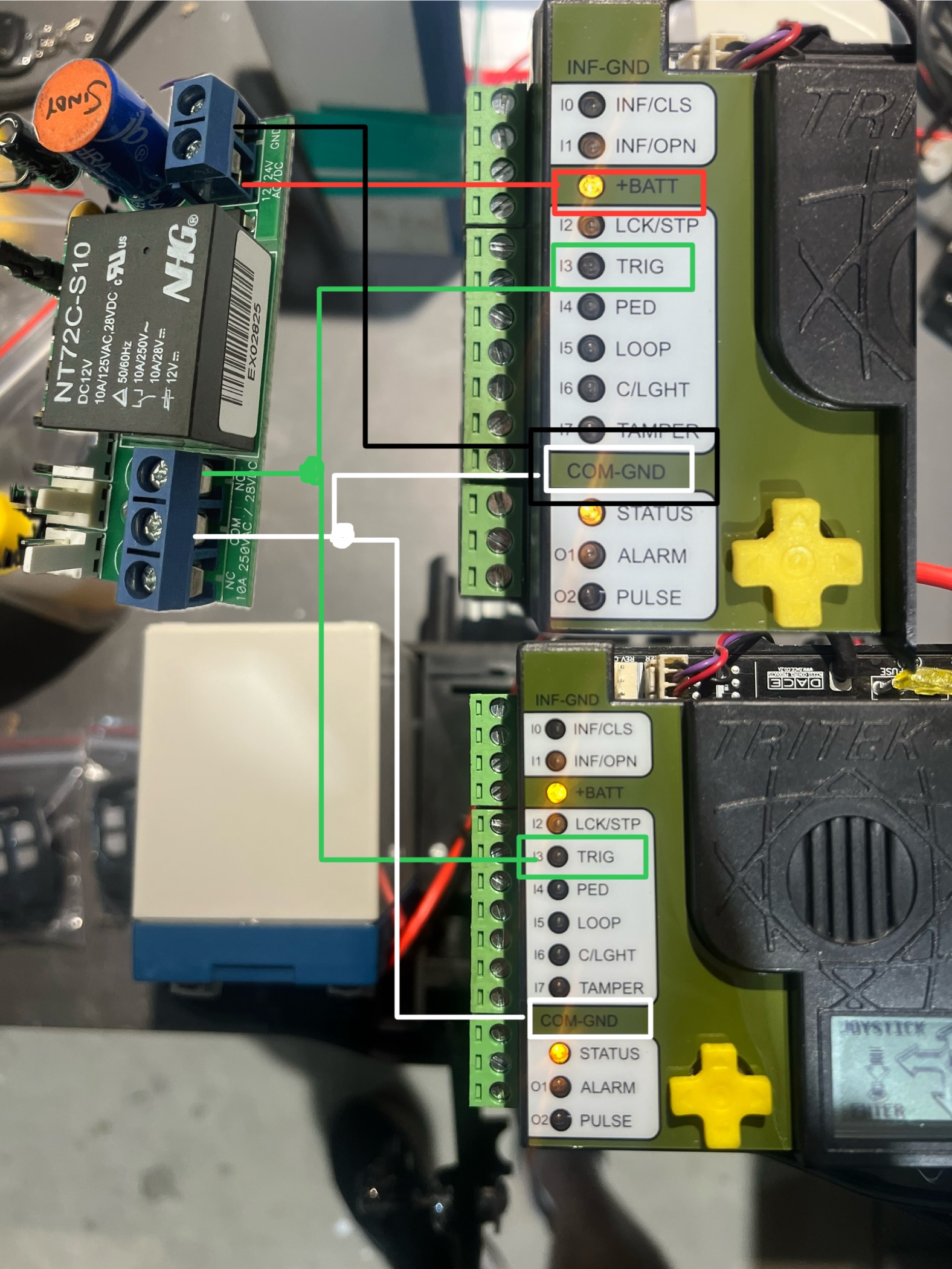
DACE Ultima Slide motor (setup as double sliding gates with 2 motors)
Wiring instructions (mud map) below if you have a double slider using 2 DACE motors. Wiring the long range receiver into each motor will help prevent the gates triggering out of sync. We would also recommend tuning one spare button on your remote to the motor as a backup incase the long range stops working.
This troubleshooting assumes that your keypad, remotes etc.. are in working order. If you have not done so already, troubleshoot these devices first!
Are there signs of insect infestation past or present inside the unit? Open up the receiver box and check there are no ants or insects past or present. If there is evidence of this then you will require a new receiver.
Check that the receiver is receiving a signal from the tuned device (keypad, push button or remote) by listening for a click sound coming from the receiver when the device is pressed. If you hear a click sound then you know you're getting power and the device is still tuned in. If you don't hear the click try re tuning the device to the receiver. see videos above for tuning help.
Is the receiver getting power and or the correct voltage required? Test with a multimeter to check power is making it to the receiver. You should be getting at least 12volts. If you don't get the correct voltage try replacing the cables. If the unit still doesn't work after new cable then you will need a new receiver.
If you are getting correct power to the receiver try removing the NO and COM cables from the receiver and tapping the bare cables together which should activate the gate. If the gate doesn't activate, replace cable.
If the gate activates when tapping the COM and NO cables together and you have the correct volts at the receiver, try re wiring the receiver and see if the unit works now. If no, then you will require a new receiver.
With the power connected to the receiver, place the black jumper link over the RELAY pins (if this is not already set).
Press and hold the remote button to be programmed to the receiver. Wait for the green light on the receiver to flash quickly.
While pressing the remote button, place the 2nd black jumper link over the REMOTE pins for 2 seconds (only) and then remove the black jumper link. Now test that the remote works.
When finished, make sure to place the 2nd black jumper back on 1 pin only.
Erasing a single remote button from receiver
You will use the button that holds the position in the receiver immediately before the one that is to be erased!!
With the power connected to the receiver, press and hold the button on the remote that was programmed to the receiver before the button that is to be erased.
Place a link over the ERASE pins. The LED will flash twice and then remain solid.
Release the remote button
Remove the link.
The remote button is now erased from the receiver.
Erasing all remotes
With the power connected to the receiver, place a link over the ERASE pins.
The LED will flash ten times and then remain on solid.
Remove the link.
The remote buttons have now been erased from the receiver.
MANUFACTURERS RECOMMENDATIONS AND COMMENTS
1. For optimum range it is advisable to place the receiver a minimum of 2
metres vertically away from the gate motor e.g. top of gate posts.
2. When placing the receiver outside of the control box or motor housing it is
important to use a weatherproof box with all entry points sealed. The standard
receiver housing is only splash proof and not suitable for outdoor applications. **
3. Make sure there are no exposed wires outside the receiver.
4. Placing the receiver inside the motor housing will reduce the range of the
receiver when the motor is in operation.
5. Range may be affected by signals transmitted from another source.
6. When coding remotes for use in a complex it is recommended that all
remotes be physically numbered and a record be kept.
* All dependent on line of sight to the gate and interference which may
reduce expected range. DO NOT ALTER THE ANTENNA IN ANY WAY (TUNED
LENGTH ANTENNA)
** Warranty will void if the receiver housing has been placed outside and not in a
recommended weatherproof box.
Tuning a remote to the long range receiver - Purple Antenna
Click on the motor you have below to see the wiring diagram:
E8 Swing motor - EGA-04 version 1 board
E8 Swing motor - EGA-04 version 2 board with on/off switch
Press and hold remote button that is to trigger the opener. It is important that this button is continuously held from step 1 through to step 3.
Place the jumper over the two LEARN pins on the PC Board for 2 seconds.
Remove the jumper from the two pins.
Release the button on the remote. That particular button on the remote is now programmed to the receiver.
ERASE ALL REMOTES
Place the jumper across the two ERASE pins
The LED will flash 4 times to warn you that the remotes will be erased after which the LED will stay solid red
When the LED remains on solid, all the remotes have been erased Remove the jumper
Tuning a remote to the long range receiver
Green Antenna
Tuning a push button to the long range receiver
Green Antenna
Click on the motor you have below to see the wiring diagram:
E8 Swing motor - EGA-04 version 1 board
E8 Swing motor - EGA-04 version 2 board with on/off switch
TMT 400LLS Swing motor
TMT 800LS Slide motor
DACE Ultima Slide motor
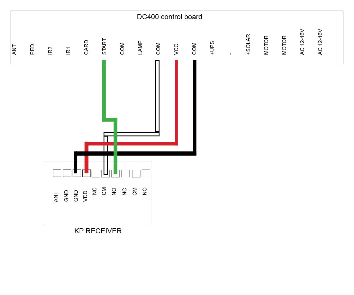
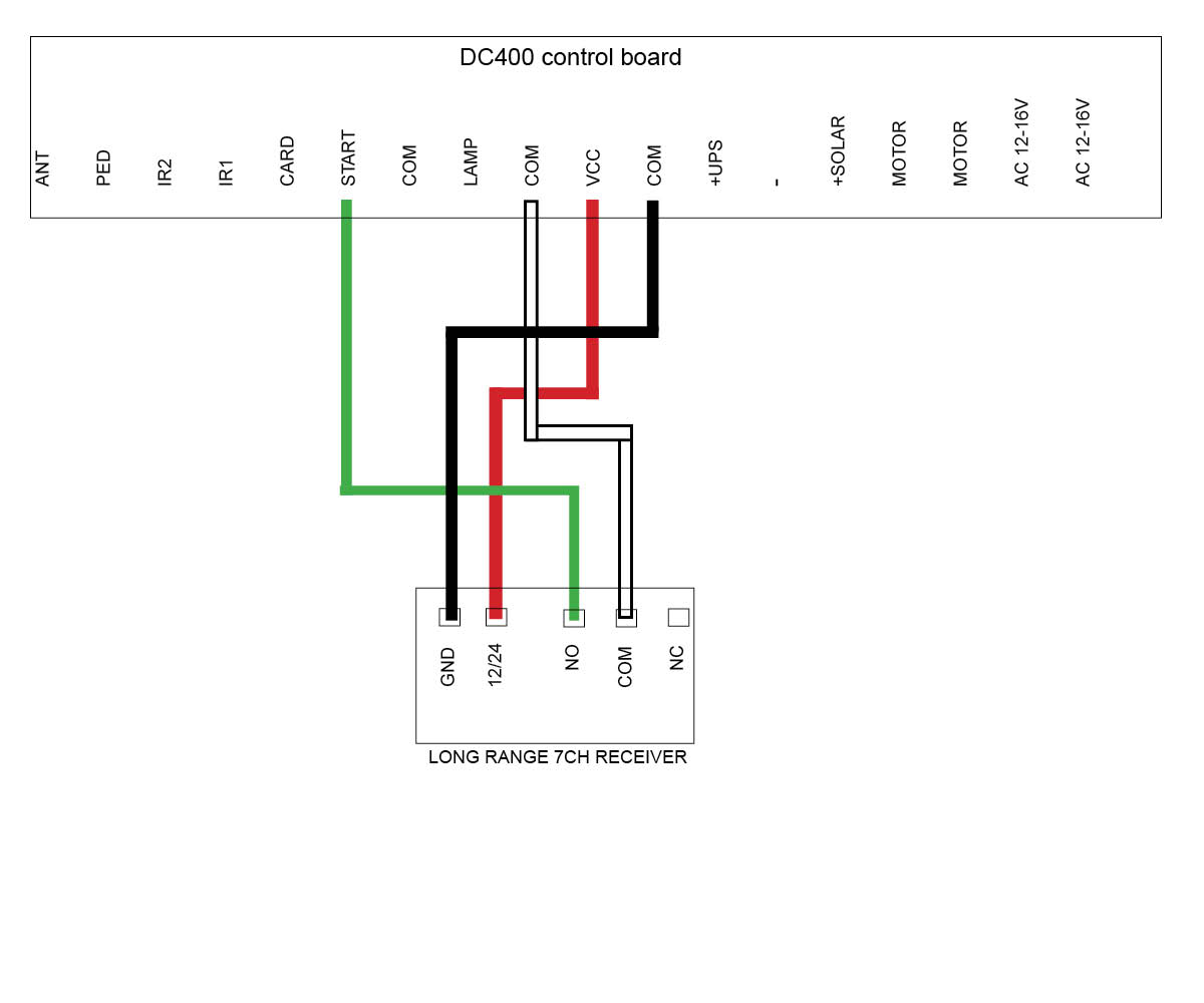
DC400 Slide motor (Discontinued)
E8 Swing motor - D1 Board (Discontinued)
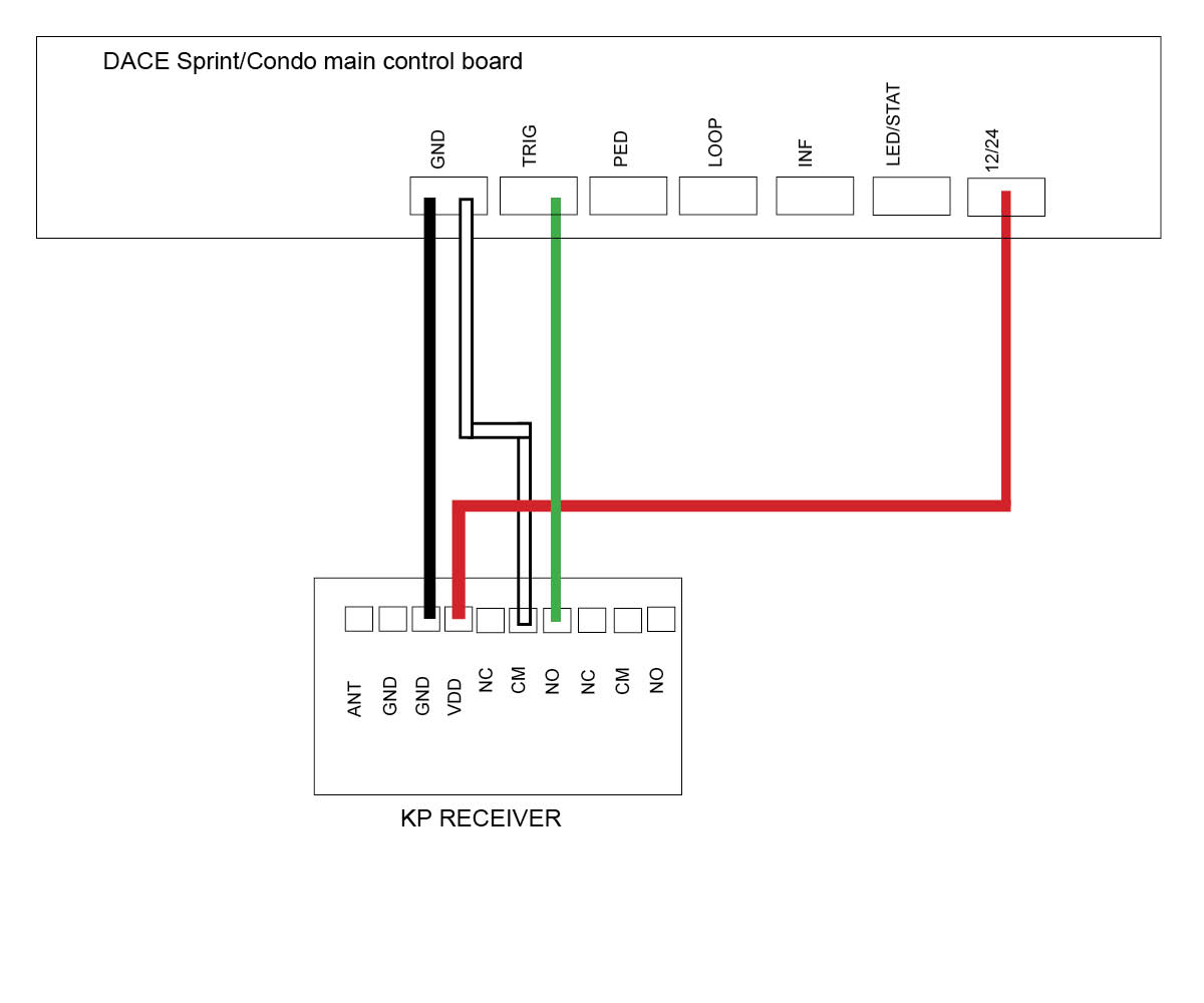
DACE Sprint/Condo Slide motor (Discontinued)
LW550 Slide motor (Discontinued)
Troubleshooting the Long Range Receiver
This troubleshooting assumes that your keypad, remotes etc.. are in working order. If you have not done so already, troubleshoot these devices first!
Are there signs of insect infestation past or present inside the unit? Open up the receiver box and check there are no ants or insects past or present. If there is evidence of this then you will require a new receiver.
Check that the receiver is receiving a signal from the tuned device (keypad, push button or remote) by listening for a click sound coming from the receiver when the device is pressed. If you hear a click sound then you know you're getting power and the device is still tuned in. If you don't hear the click try re tuning the device to the receiver. see videos above for tuning help.
Is the receiver getting power and or the correct voltage required? Test with a multimeter to check power is making it to the receiver. You should be getting at least 12volts. If you don't get the correct voltage try replacing the cables. If the unit still doesn't work after new cable then you will need a new receiver.
If you are getting correct power to the receiver try removing the NO and COM cables from the receiver and tapping the bare cables together which should activate the gate. If the gate doesn't activate, replace cable.
If the gate activates when tapping the COM and NO cables together and you have the correct volts at the receiver, try re wiring the receiver and see if the unit works now. If no, then you will require a new receiver.
Tuning remote to the E8 Swing board - EGA version 1 Your remote must have an orange/yellow light show when pressing Button A (no other colour will work)
Tuning remote to the E8 Swing board - EGA version 2 Your remote must have an orange/yellow light show when pressing Button A (no other colour will work)
Tuning remote to the 7CH long range receiver (purple antenna)
Tuning remote to the long range receiver (green antenna)
Tuning remote to the Ultima DACE motor open/close and pedestrian Your remote must have an orange/yellow light show when pressing Button A (no other colour will work)
Tuning remote to DC400 slide motor - This remote must have a blue light when you press any of the remote buttons.
Troubleshooting your remote
Do any other remotes work? if yes and it is only the one remote not working, try changing the battery. If the light comes on on the remote and it still doesn't work you can try re tuning to the device. If it still doesn't work then you will need a new remote. If all remotes don't work then you will need to troubleshoot your receiver.
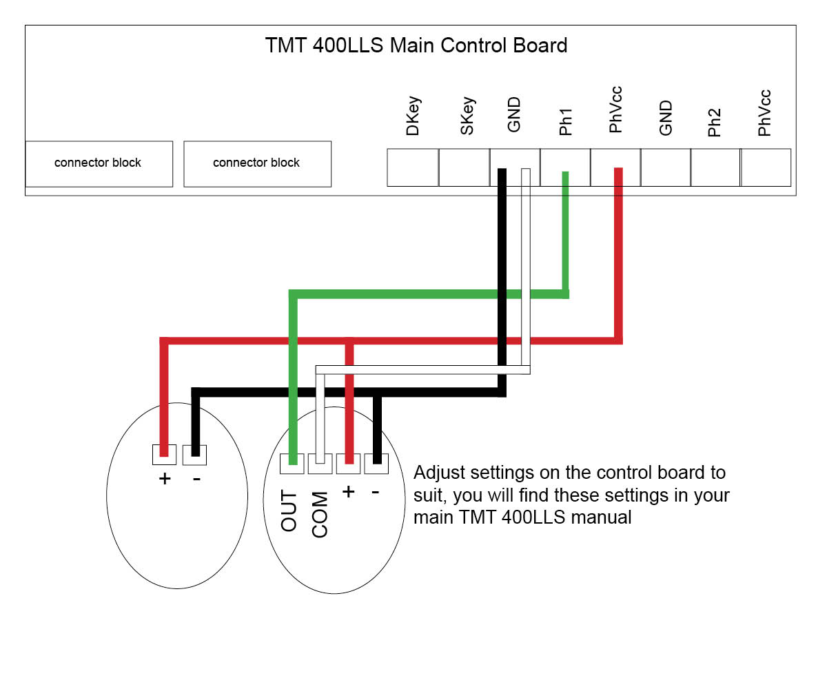
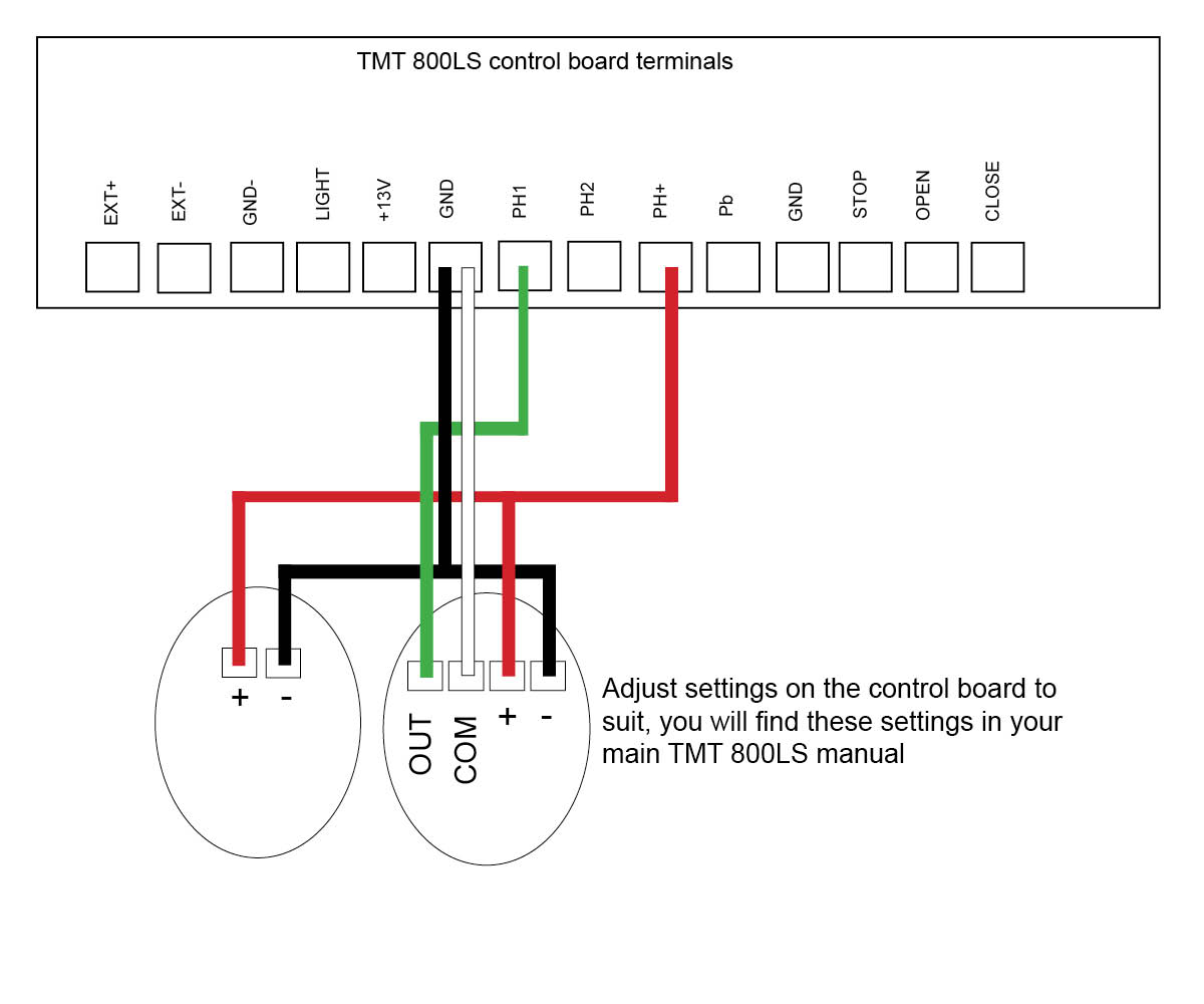
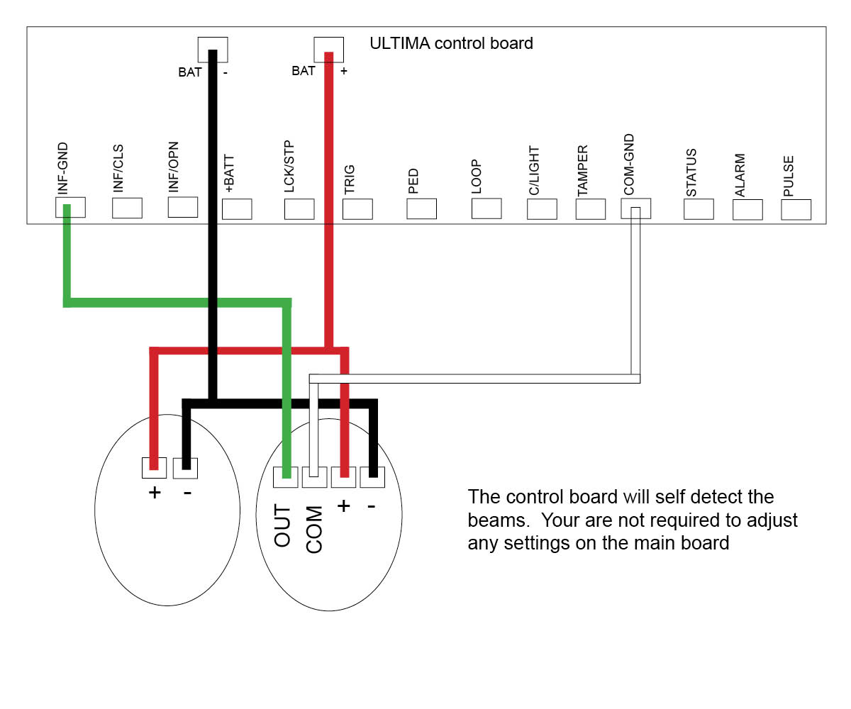
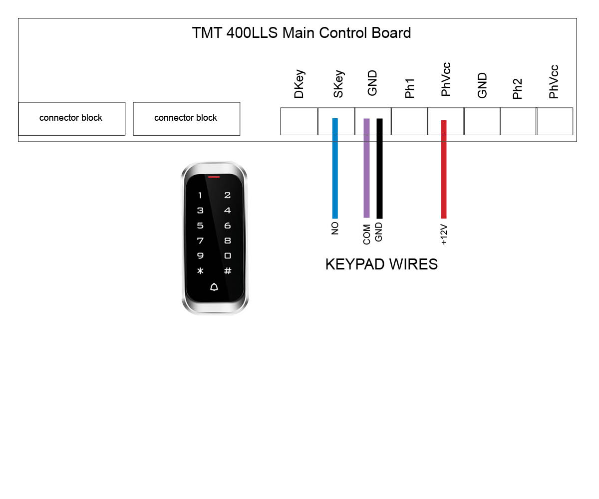
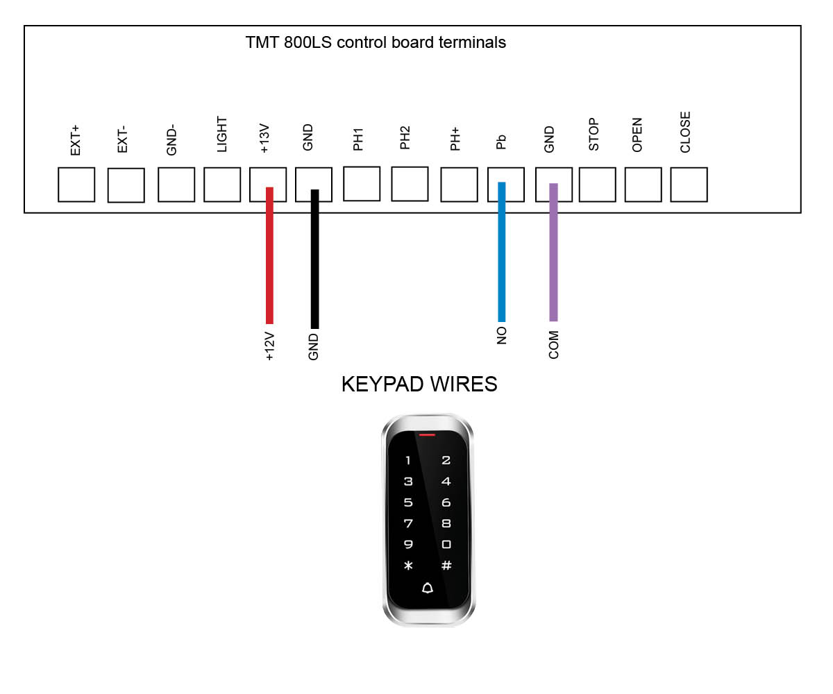
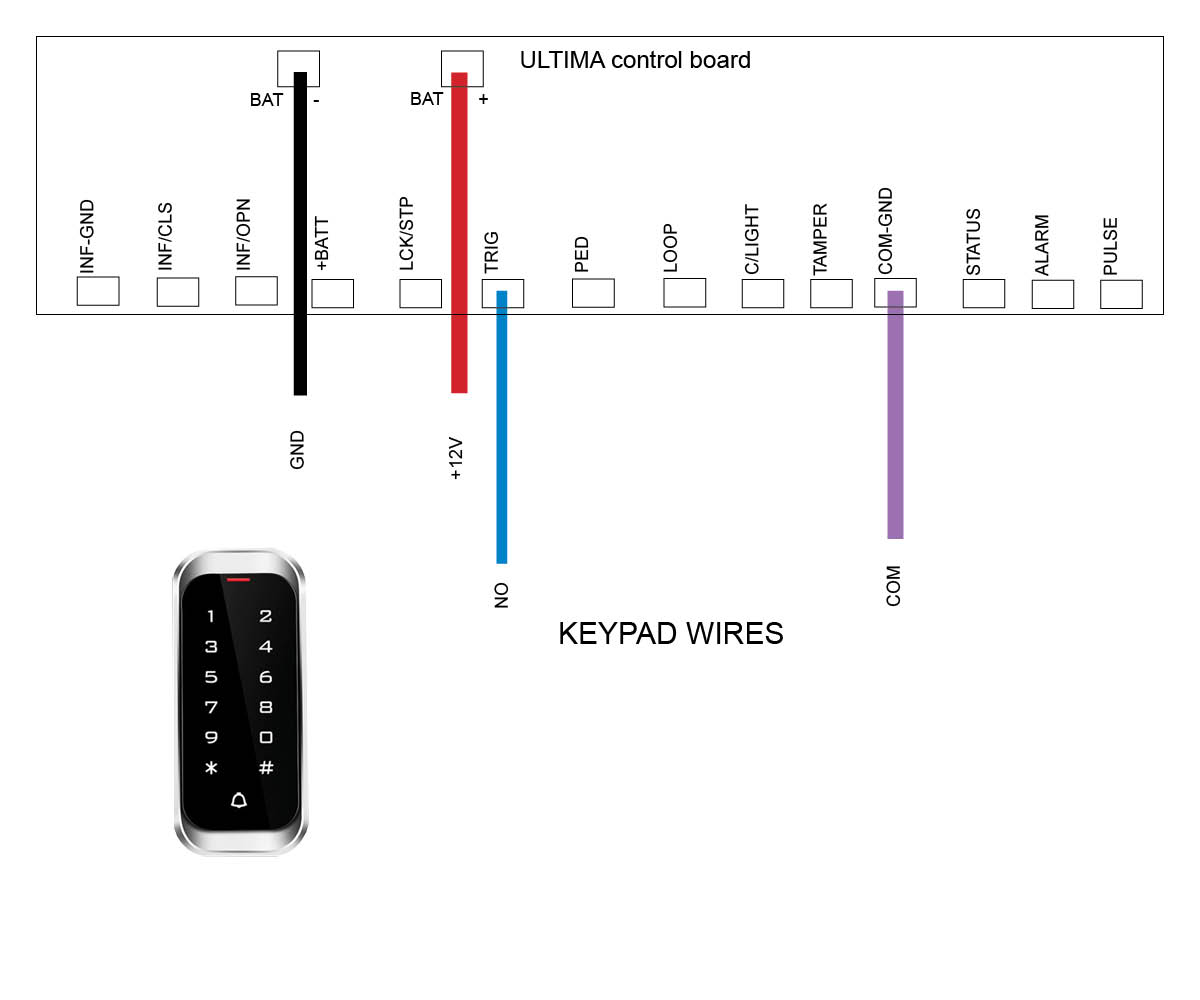
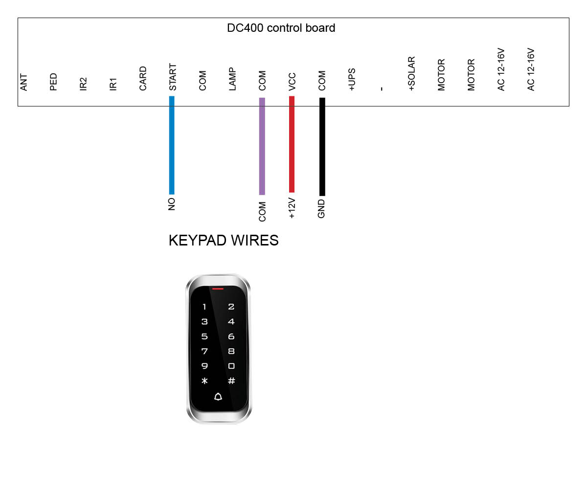
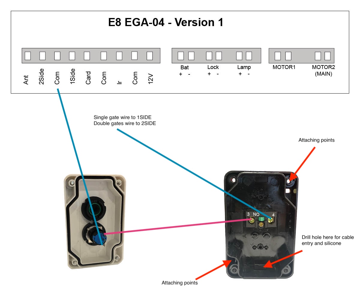
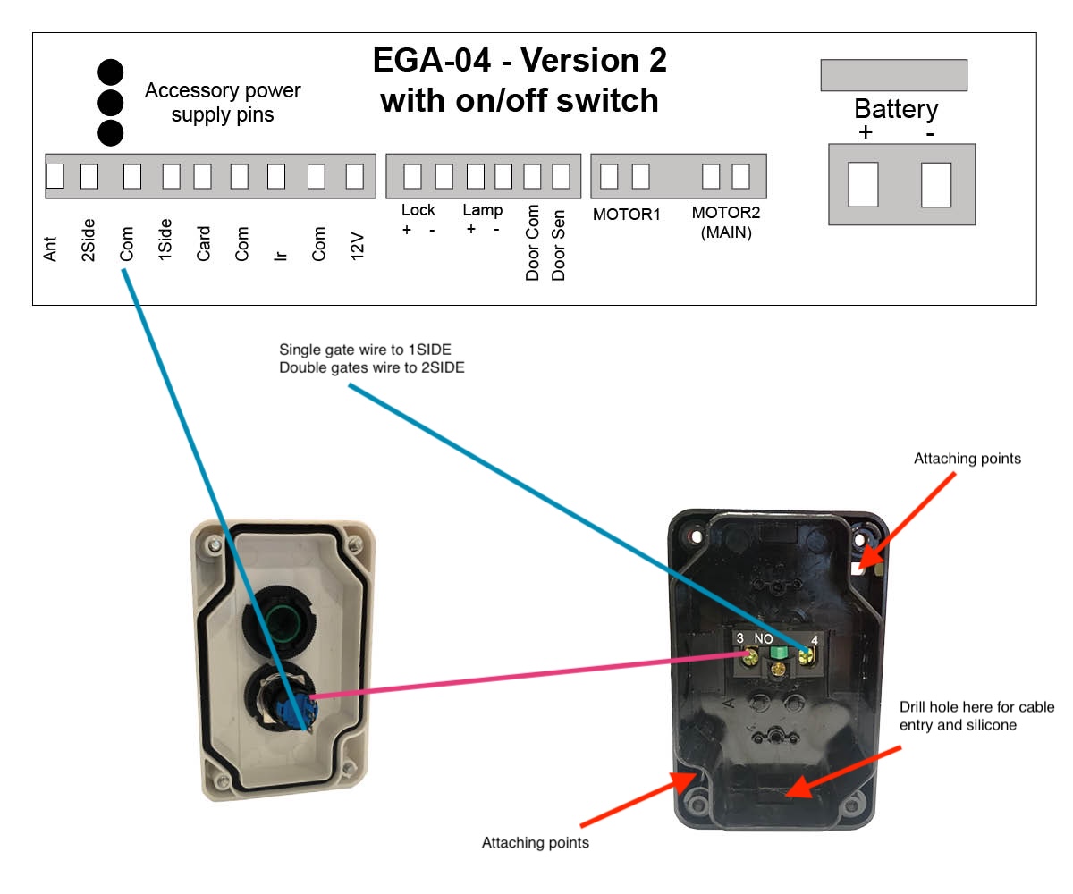
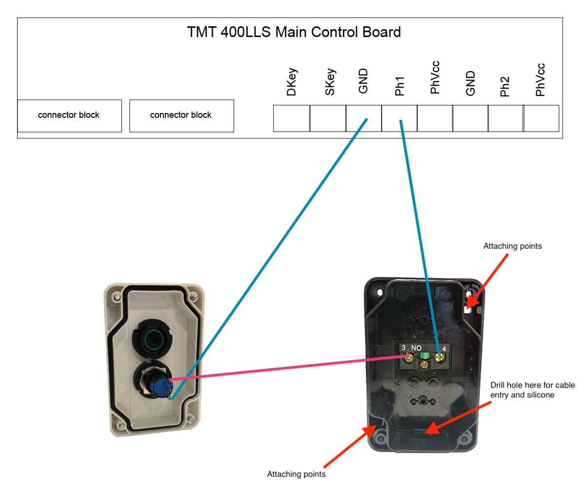
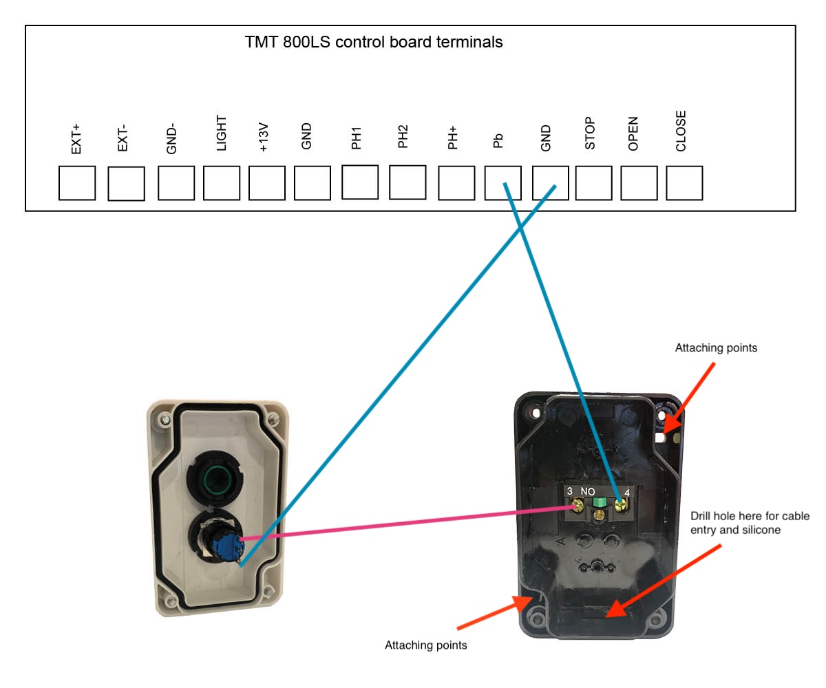
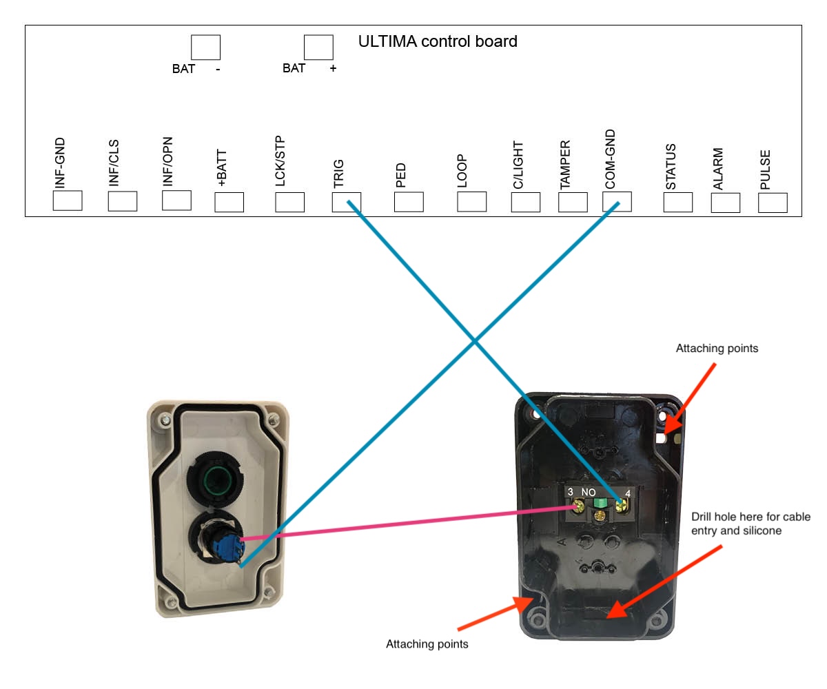
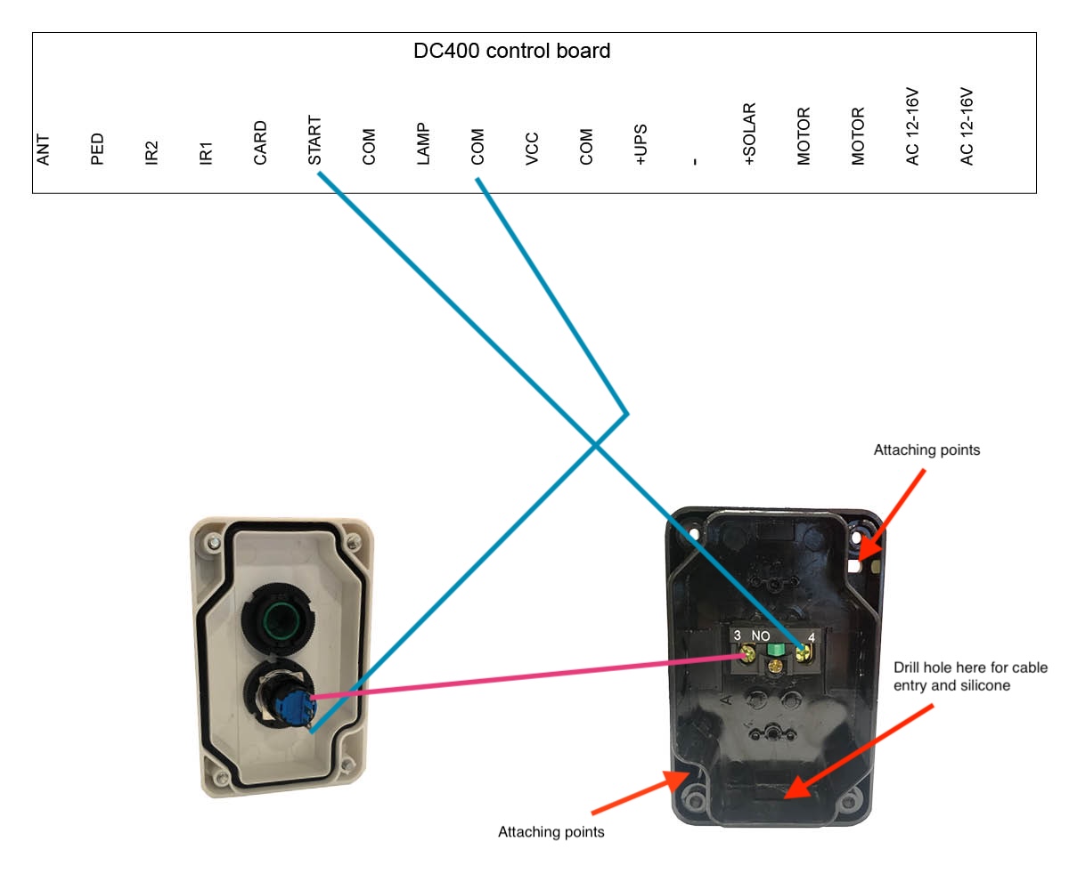
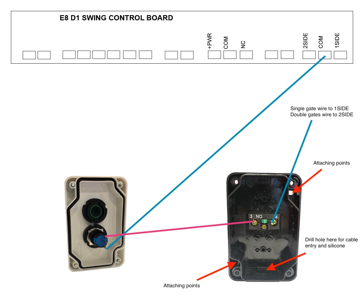
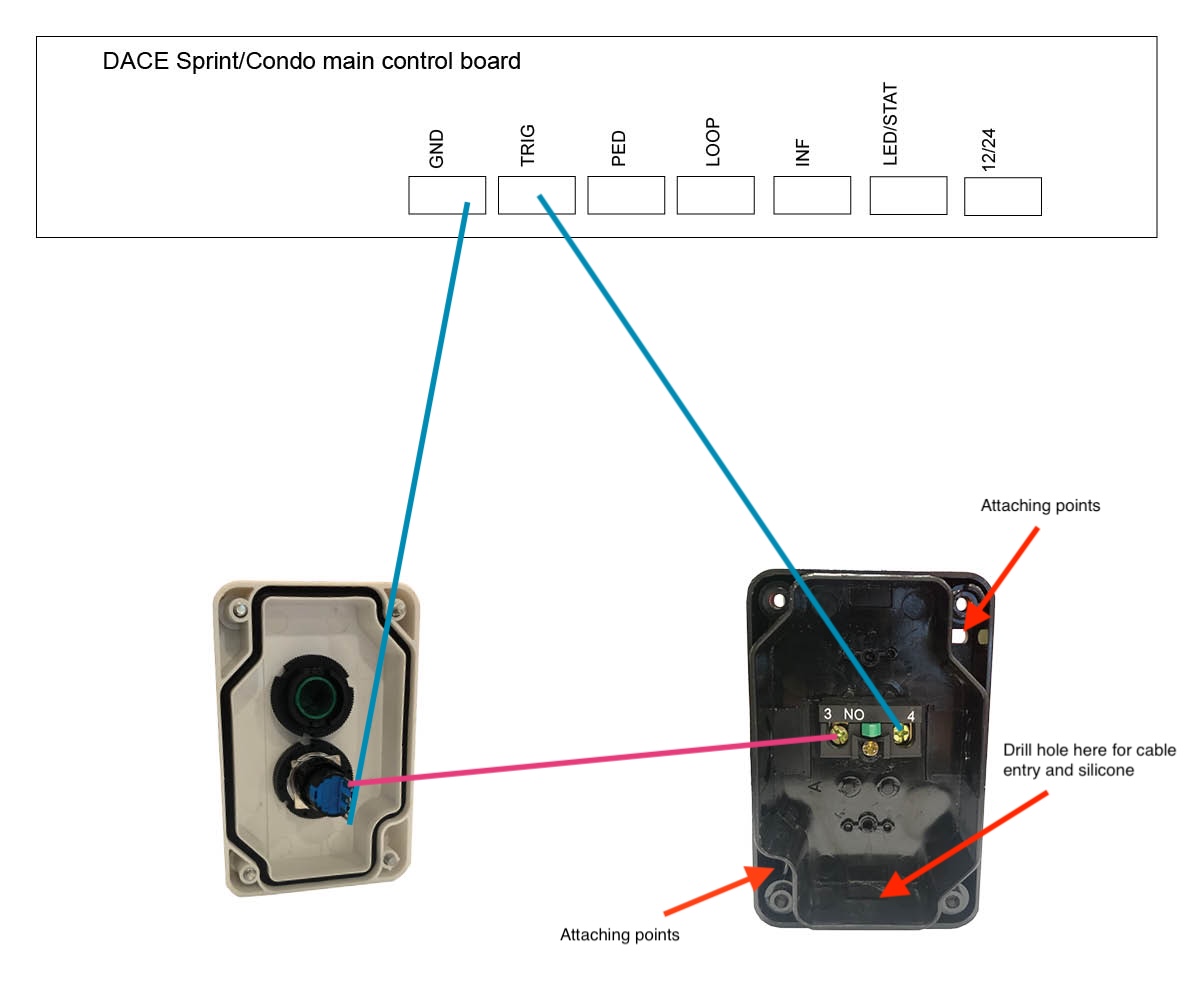
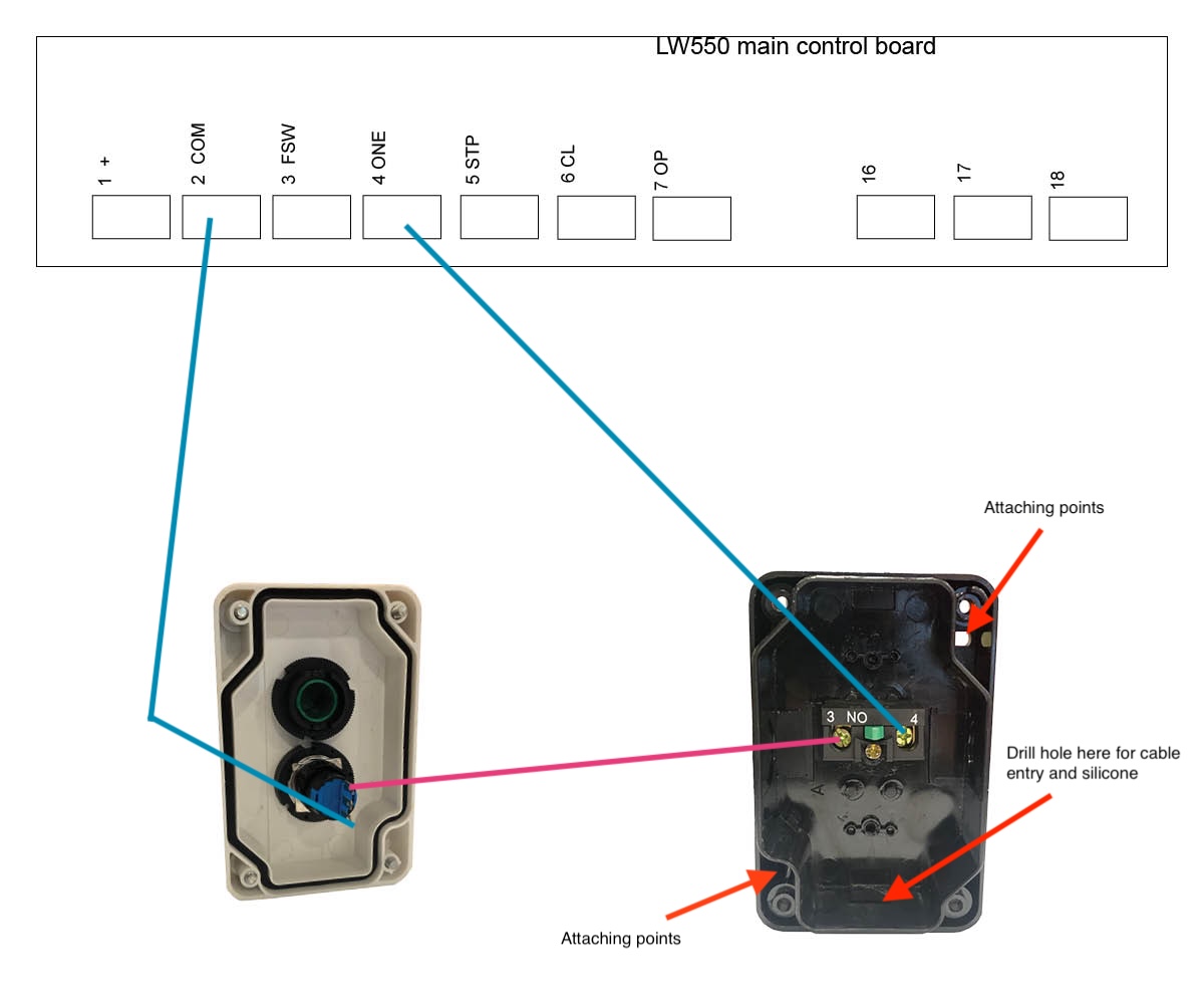
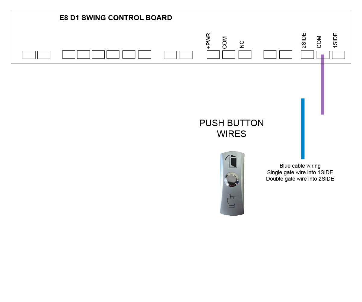
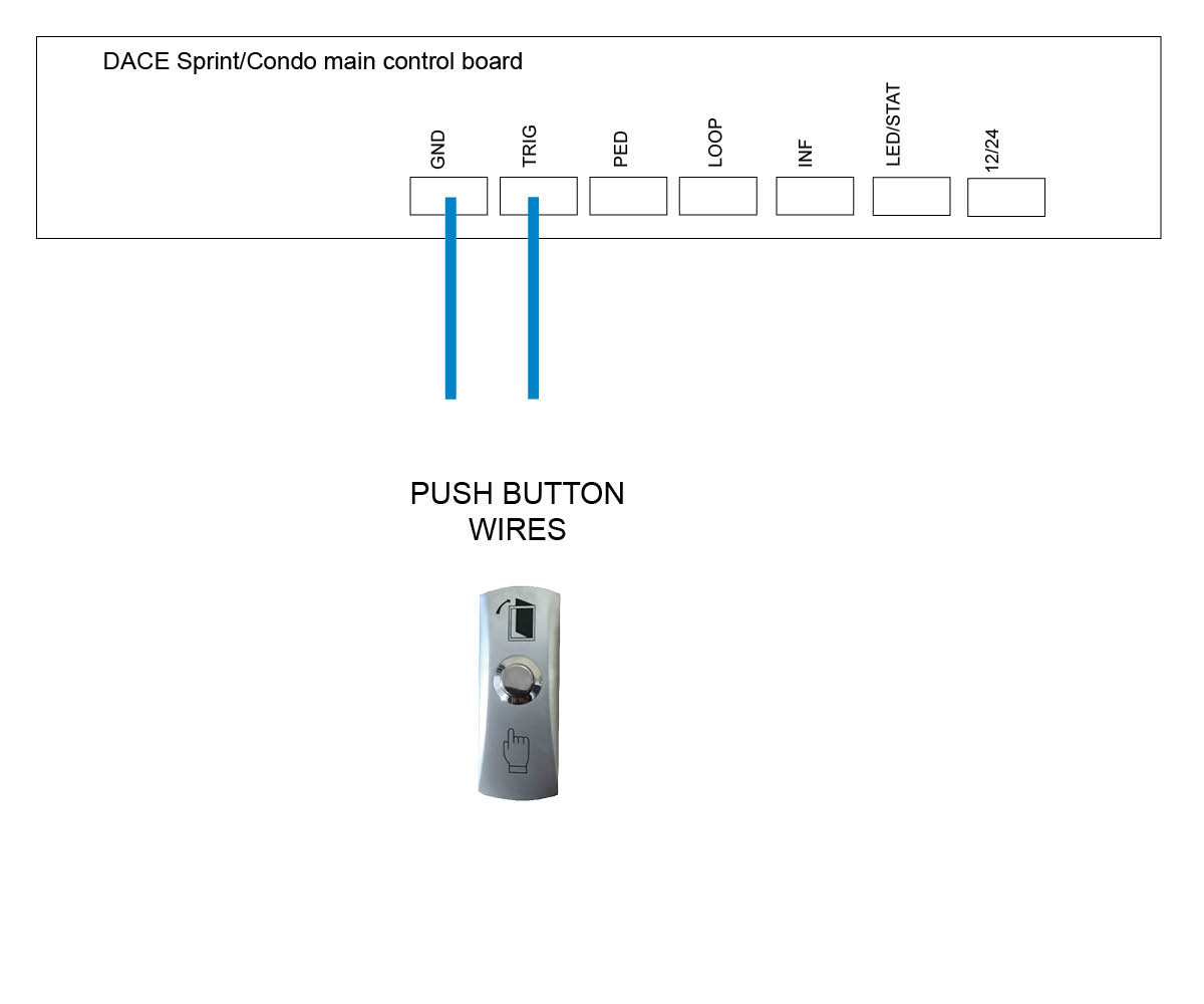
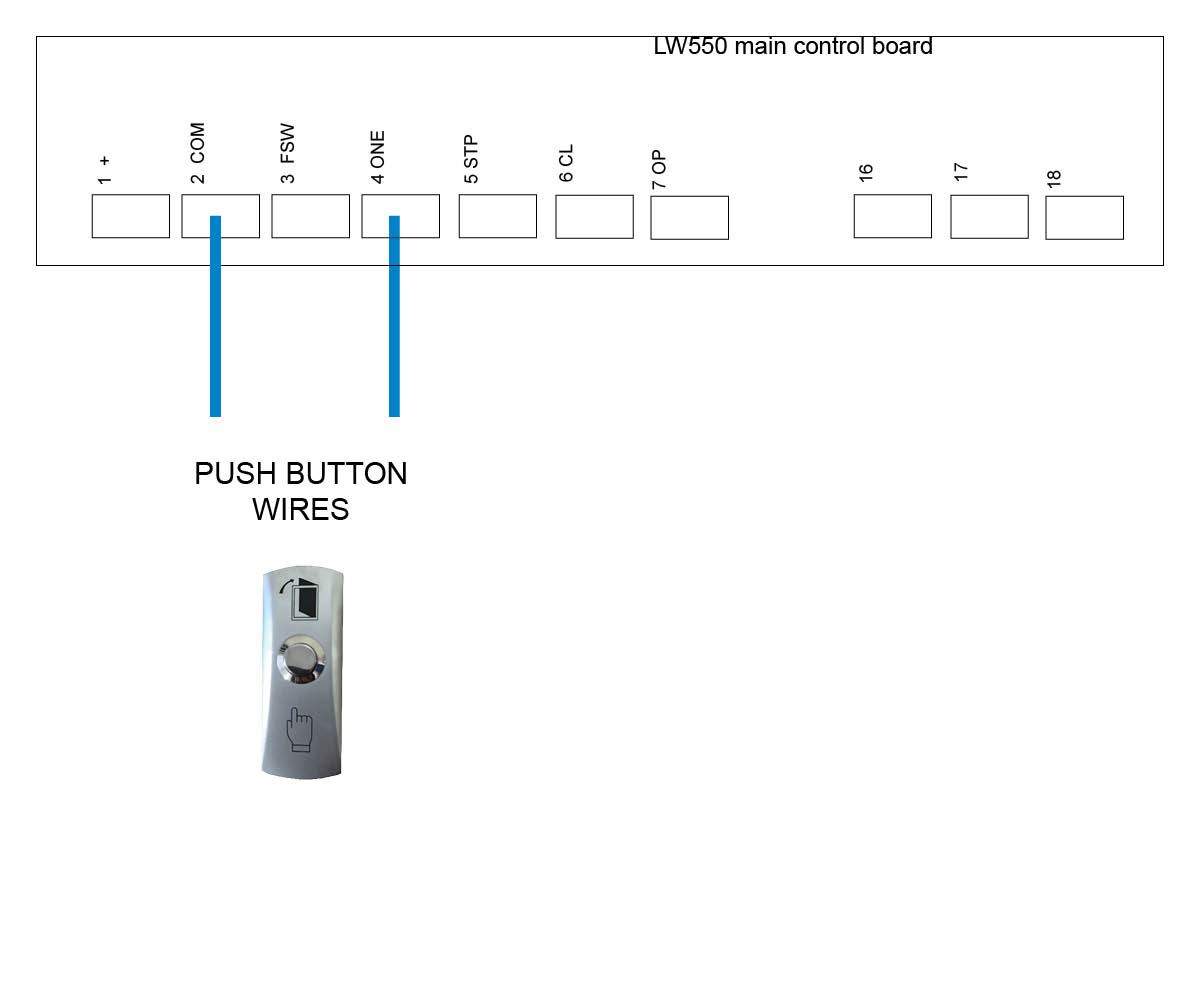
Please note that the coloured cables in our below images are for examples only and may not match the coloured cables that you will be using.
When wiring up the push button, you will be able to use the key to lock and disable the button.
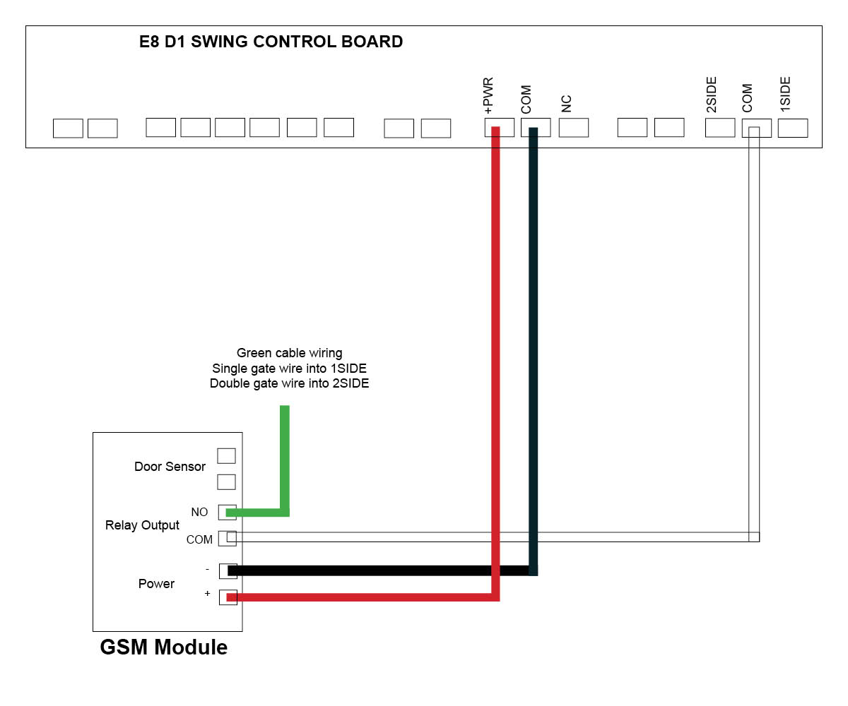
Follow both coloured wiring instructions (pink and blue) as shown below.
When securing the blue and pink cable to the internal pins of the lock you can either secure by soldering the cable, threading cable through the hole to secure it or secure cable with a connector.
When you attach the push button unit to your post, even though the button housing is a sealed unit, we highly recommend sealing (silcone) all the way around the back housing to prevent any water or insects entering in through your screws. Also when you drill the hole for your cabling at the bottom of the unit we recommend to silcone up that entry point.
We recommend every 6-12 months to do a thorough check over the push button and it’s internals to make sure there is no insect infestation and that everything is still in good working order.
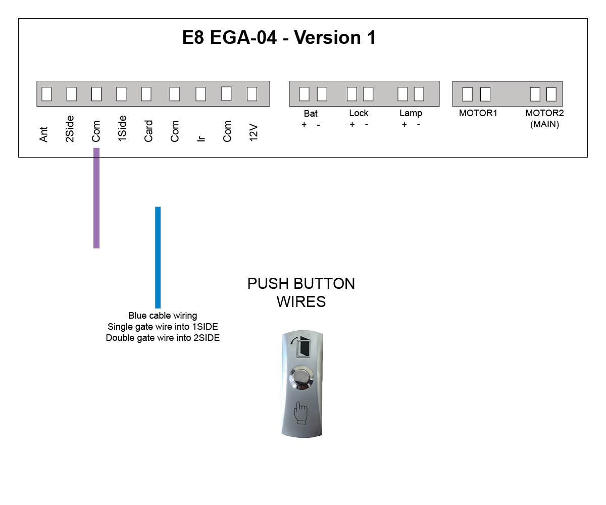
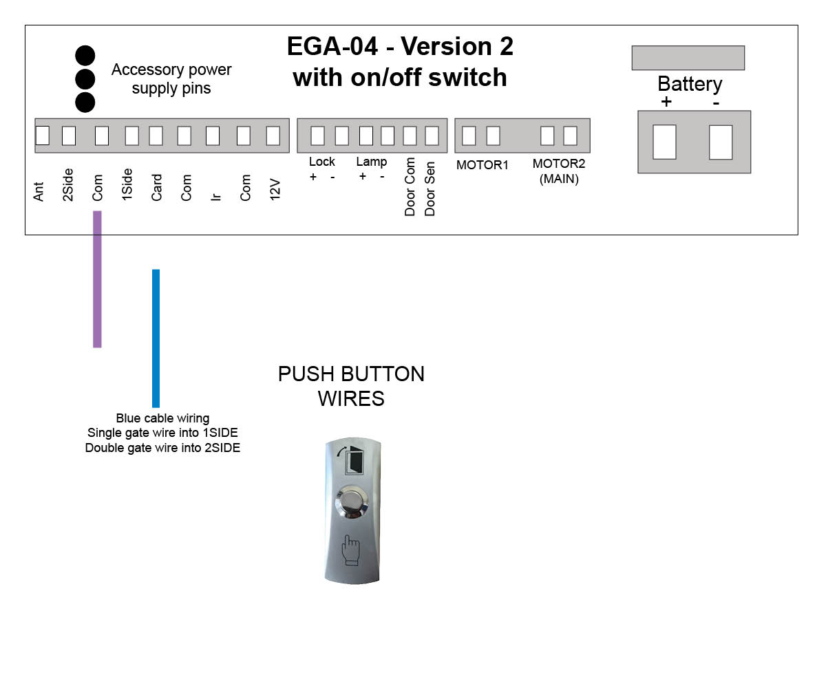
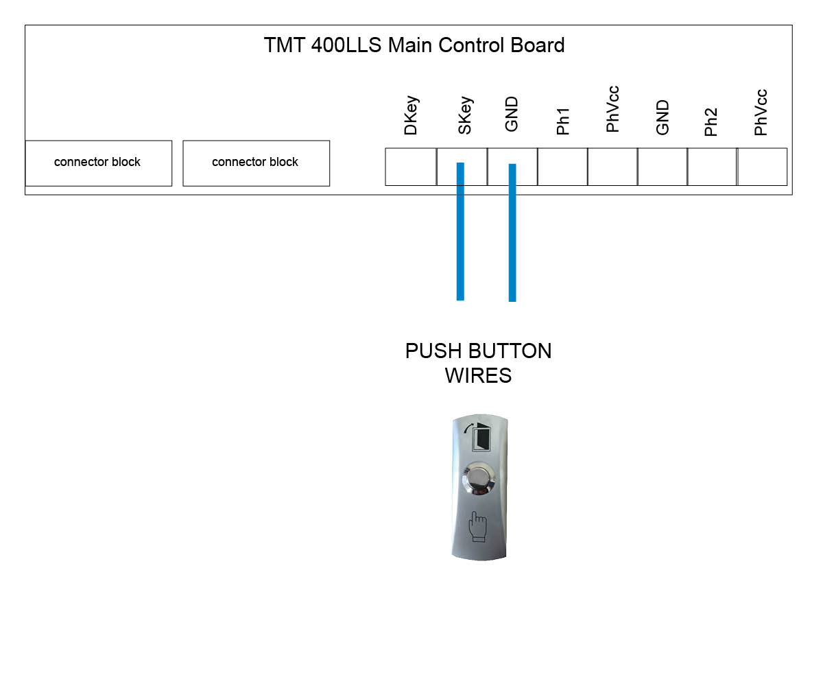
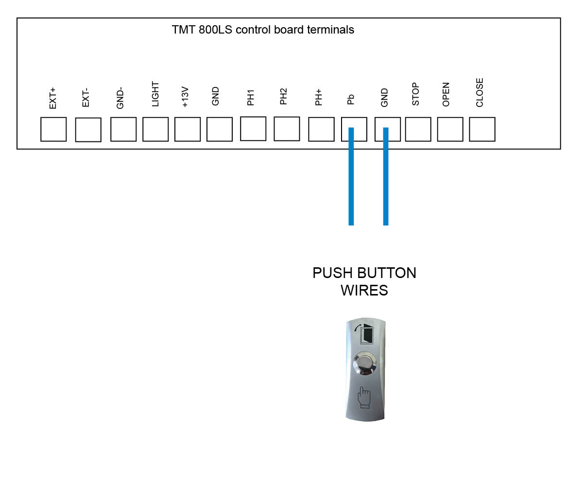
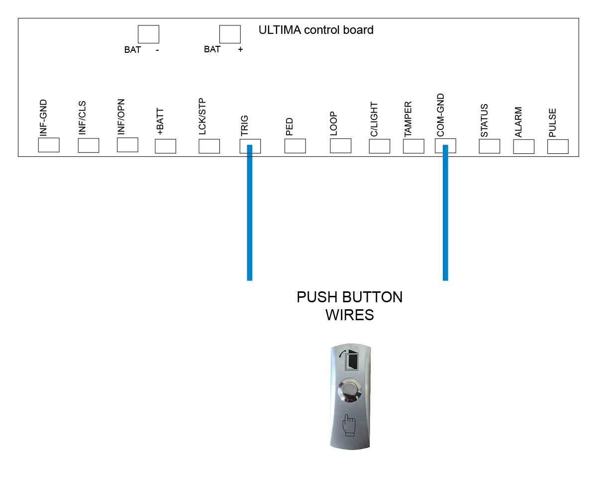
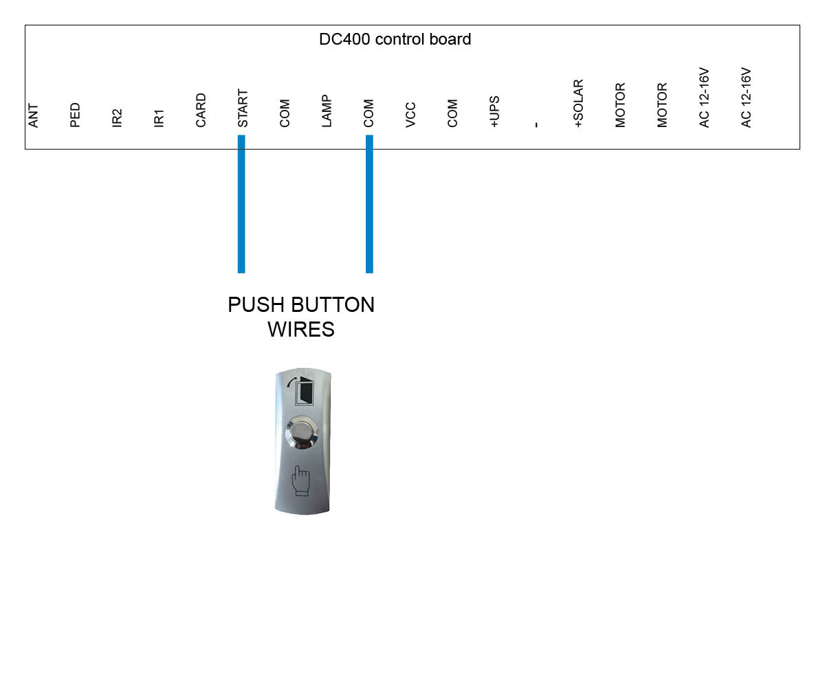
Blue cables
These will wire directly to the main control board, please refer to your user manual or see diagrams below.
Unit Attaching Points
We recommend attaching the push button via the attaching points indicated with a red arrow shown in the below images.
Please be aware that failure to perform the recommendations above will void your warranty.
Click on the motor you have below to see the wiring diagram:
E8 Swing motor - EGA-04 version 1 board
E8 Swing motor - EGA-04 version 2 board with on/off switch
TMT 400LLS Swing motor
TMT 800LS Slide motor
DACE Ultima Slide motor
DC400 Slide motor (Discontinued)
E8 Swing motor - D1 Board (Discontinued)
DACE Sprint/Condo Slide motor (Discontinued)
LW550 Slide motor (Discontinued)
Troubleshooting your hard wired push button
Check for insect infestation in your push button housing
Check cabling by removing the cable from the push button and tapping them together - this should activate the gate. Re wire to the push button and see if it works.
Try contact spray or WD40 on the internal connectors and see if this helps
If the above help doesn't reslove the issue you will need a new push button.
We recommend attaching the push button via the attaching points as indicated with a red arrow shown in the image.
When you attach the push button unit to your post, even though the button housing is a sealed unit, we highly recommend sealing (silcone) all the way around the back housing to prevent any water or insects entering in through your screws.
The battery required for this device is a 12v 27A
We recommend every 6-12 months to do a thorough check over the push button and it’s internals to make sure there is no insect infestation and that everything is still in good working order.
Please be aware that failure to perform the recommendations above will void your warranty.
Only wireless push buttons purchased from July 2022 and onwards are able to tune to the E8-EGA control board and Ultima kits
Tuning to the swing EGA control board
Tuning to the DACE Ultima board - Use the KP receiver on solar
Tuning to a long range receiver
Tuning to the KP receiver
Troubleshooting your wireless push button
Do you have insect infestation (past or present) in your push button housing? If yes, then you will require a new push button.
If you press the small green knob inside the push button, does the internal orange light show on the small remote board? If yes you can try re tuning your button to your device in case it has dropped out. If no, try pressing the small white button on the remote board, now does the orange light come on? if yes, try re wiring the internal PCB to the button incase it doesn't have a good connection. If no, try replacing the internal battery. If you replace the internal battery and still no orange light shows, you will need a new push button.
Your push button may be tuned to a separate receiver which you will need to check - if there is no separate receiver then your button will be tuned direct to the main control board of the motor
If you have a separate receiver, do you have the KP receiver or long range receiver? see troubleshooting for each receiver below.
Are there signs of insect infestation past or present inside the unit? Open up the receiver box and check there are no ants or insects past or present. If there is evidence of this then you will require a new receiver.
Check that the receiver is receiving a signal from the push button by listening for a click sound coming from the receiver when the device is pressed. If you hear a click sound then you know you're getting power and the device is still tuned in. If you don't hear the click try re tuning the device to the receiver. see videos above for tuning help.
Is the receiver getting power and or the correct voltage required? Test with a multimeter to check power is making it to the receiver. You should be getting at least 12volts. If you don't get the correct voltage try replacing the cables. If the unit still doesn't work after new cable then you will need a new receiver.
If you are getting correct power to the receiver try removing the NO and COM cables from the receiver and tapping the bare cables together which should activate the gate. If the gate doesn't activate, replace cable.
If the gate activates when tapping the COM and NO cables together and you have the correct volts at the receiver, try re wiring the receiver and see if the unit works now. If no, then you will require a new receiver.
Are there signs of insect infestation past or present inside the unit? Open up the receiver box and check there are no ants or insects past or present. If there is evidence of this then you will require a new receiver.
Check that the receiver is receiving a signal from the tuned device (keypad, push button or remote) by listening for a click sound coming from the receiver when the device is pressed. If you hear a click sound then you know you're getting power and the device is still tuned in. If you don't hear the click try re tuning the device to the receiver. see videos above for tuning help.
Is the receiver getting power and or the correct voltage required? Test with a multimeter to check power is making it to the receiver. You should be getting at least 12volts. If you don't get the correct voltage try replacing the cables. If the unit still doesn't work after new cable then you will need a new receiver.
If you are getting correct power to the receiver try removing the NO and COM cables from the receiver and tapping the bare cables together which should activate the gate. If the gate doesn't activate, replace cable.
If the gate activates when tapping the COM and NO cables together and you have the correct volts at the receiver, try re wiring the receiver and see if the unit works now. If no, then you will require a new receiver.
We recommend attaching the push button via the attaching points as indicated with a red arrow shown in the image.
When you attach the push button unit to your post, even though the button housing is a sealed unit, we highly recommend sealing (silcone) all the way around the back housing to prevent any water or insects entering in through your screws.
We recommend every 6-12 months to do a thorough check over the push button and it’s internals to make sure there is no insect infestation and that everything is still in good working order.
Please be aware that failure to perform the recommendations above will void your warranty.
Pairing the KP Receiver to the wireless push button
Press P1 on the receiver board (red LED will go solid)
Press and hold the push button for 3 seconds (red LED will flash to say push button and receiver are paired)
Deleting KP recevier memory
Press P2 on the receiver board for 8 seconds (red LED will go solid,
push button and receiver are now unpaired)
How to pair a wireless button to the KP Receiver
Click on the motor you have below to see the wiring diagram for the KP Receiver:
E8 Swing motor - EGA-04 version 1 board
E8 Swing motor - EGA-04 version 2 board with on/off switch
We recommend attaching the push button via the attaching points as indicated with a red arrow shown in the image.
When you attach the push button unit to your post, even though the button housing is a sealed unit, we highly recommend sealing (silcone) all the way around the back housing to prevent any water or insects entering in through your screws.
We recommend every 6-12 months to do a thorough check over the push button and it’s internals to make sure there is no insect infestation and that everything is still in good working order.
Please be aware that failure to perform the recommendations above will void your warranty.
Programming a button
With the power connected to the receiver, place the black jumper link over the RELAY pins (if this is not already set).
Press and hold the button to be programmed to the receiver. Wait for the green light on the receiver to flash quickly.
While pressing the button, place the 2nd black jumper link over the REMOTE pins for 2 seconds (only) and then remove the black jumper link. Now test that the remote works.
When finished, make sure to place the 2nd black jumper back on 1 pin only.
Erasing all buttons
Note: deleting an accessory from this receiver will delete all accessories tuned in. You will be required to tune any other items back in that you still require.
With the power connected to the receiver, place a link over the ERASE pins.
The LED will flash ten times and then remain on solid.
Remove the link.
The buttons have now been erased from the receiver.
LONG RANGE RECEIVER - MANUFACTURERS RECOMMENDATIONS AND COMMENTS
1. For optimum range it is advisable to place the receiver a minimum of 2
metres vertically away from the gate motor e.g. top of gate posts. 2. When placing the receiver outside of the control box or motor housing it is
important to use a weatherproof box with all entry points sealed. The standard
receiver housing is only splash proof and not suitable for outdoor applications. **3. Make sure there are no exposed wires outside the receiver.4. Placing the receiver inside the motor housing will reduce the range of the
receiver when the motor is in operation.5. Range may be affected by signals transmitted from another source.
* All dependent on line of sight to the gate and interference which may
reduce expected range. DO NOT ALTER THE ANTENNA IN ANY WAY (TUNED
LENGTH ANTENNA)
** Warranty will void if the receiver housing has been placed outside and not in a
recommended weatherproof box.
Tuning a push button to the long range receiver - Purple Antenna
Click on the motor you have below to see the wiring diagram:
E8 Swing motor - EGA-04 version 1 board
E8 Swing motor - EGA-04 version 2 board with on/off switch
If you require extra security on your keypad, then it is recommended that you change the factory program code (0000) to a secure code which you must make note of. Failing to make note of your new program code will prevent you from being able to add or delete pin codes in the future. You would then be required to perform the 'Keypad reset'.
Factory pin code in the keypad to start off with is 1111#. When entering in your first pin code the factory pin code will be wiped.
OLD MODEL
NEW MODEL (END 2024)
Important: New model keypads from late April 2025 will now be compatible with our TMT Kits.
Details below will show you how to switch the keypad between (factory setting) E8 and DACE kits to the TMT kits.
Tips:
We recommend charging your keypad before installing.
If you hear 2 beeps during programming then you have made a mistake.
Red light on is the charger indicator. It lights up when charging and goes out when fully charged.
Green light is the transmitting indicator, which lights up when transmitting a signal.
Blue light is the programming indicator and it will keep flashing when your are entering the programming mode. The blue light will only stay on solid if the keypad is locked out.
Becareful when installing the keypad onto your post that you don't overtighten the screws. Doing so will distort the keypad housing and allow water to seep through and void your warranty.
To work with E8 and DACE kits
Enter program code (Factory 0000) then press *
Press 7 7 #
Press 0 1 #
To work with BMG's TMT kits
Enter program code (Factory 0000) then press *
Press 7 7 #
Press 0 2 #
Setting up a 4 digit pin code in your keypad
Enter program code (Factory 0000) then press *
Press 0 1 #
Enter your pin code = ? ? ? ? # (pin code now entered)
Setting up Swipe Card or Tag (NEW MODEL ONLY)
Enter program code (Factory 0000) then press *
Press 0 1 #
Swipe card or tag then press #
Delete a single pin code from the keypad
Enter program code (Factory 0000) then press *
Press 5 8 #
Enter 4 digit pin number # that you want to delete (keypad will give 1
long beep followed by a short beep to indicate the pin code deleted)
Erasing all pin codes from the keypad
Enter your program code (Factory is 0000) then press *
Press 0 0 #
Now all pin codes will be wiped and set back to the factory pin code 1111#
Battery test
Enter program code (Factory 0000) then press *
Press 8 9 # (battery is OK with a long beep or if battery is low there will
be a short beep and the red LED indicator will show)
Turn off/on keypad backlight
Enter program code (Factory 0000) then press *
Press 3 9 #
RF Signal Delay (NEW MODEL ONLY)
This is used if you are having trouble tuning the keypad to a receiver and you need the delay extended to allow the keypad to tune.
Enter program code (Factory 0000) then press *
Press 41 # (keypad will sound a long beep)
Select on of the following 01#=.5sec delay 02#=1sec delay 03#=1.5sec delay 04#=2sec delay
Now try tuning your keypad to the receiver.
10 Second Continuous Signal
This is used if you are having trouble tuning the keypad to a device and require a longer signal.
Enter program code (Factory 0000) then press *
Press 55 # (keypad will sound a long beep)
Press 01 # (if using channel 2 press 02 #)
Now proceed to tune keypad to your device
Keypad resetting (OLD MODEL KEYPAD)
Remove the keypad from weather shield
Your keypad should now be awake with the alarm activated
While the keypad alarm is going off, press the reset button located on top of the keypad for 5 seconds until all LED lights come on
Now release the reset button, resetting is now complete (all keypad codes
will be cleared and reset to factory)
Place the keypad back into the weather shield
The keypad will now be reset to 0000 program code and 1111 factory pin code.
Keypad resetting (NEW MODEL)
Remove the button dust plug from the back case, use a small pin or other object to press and hold the button for about 10 seconds or until you hear the buzzer make a long beep sound, the reset operation is successful. Now all pin codes and parameters are reset to factory default and all pin codes and swing cards/tags have been deleted.
Security lock mode
When the keypad enters the programming mode or transmits an RF signal the keypad allows up to 4 incorrect attempts. When an incorrect pin code is entered for the 5th time the blue light will stay on and the keypad will be locked for 2 minutes. This prevents illegal users from trying to open the gate via the pin code. The keypad unlocks automatically after 2 mintues.
Changing the 4 digit ‘program code’ (0000)
Your program code only requires to be changed if you require extra security on your keypad. You will need to take note of your program code as this will be used to add or delete pin codes in the future.
Enter program code = 0 0 0 0 *
Press 6 9 #
Enter new 4 digit program mode code #
BEAWARE this will override the 0000* so you must remember this code
Watch our videos below to help with programming and tuning your keypad to the correct device
How to add a pin number
How to tune your keypad to the KP Receiver
How to tune your keypad to the E8 EGA Board
How to tune your keypad to the LR Receiver
How to tune your keypad to the Ultima (Electric)
How to tune your keypad to the TMT 400LLS
How to tune your keypad to the TMT 800LS
Troubleshooting your keypad (old style AA batteries)
Are there signs of insect infestation past or present inside the unit? If yes then you will require a new keypad. If no, are there any signs of corrosion? If there are signs of corrosion you will need a new keypad.
If there is no corrosion or insect infestation past or present, try changing batteries. If you changed the batteries and no lights have come on and the keypad doesn't activate at all then you will require a new keypad. If you changed the AA batteries and you enter your pin number does the middle light come on the keypad but the gate still doesn't operate? If yes then try tuning your keypad back to the device incase it has dropped out.
For further assistance please contact the office
Troubleshooting your keypad (new style with Lithium Battery)
Have you tried charging your keypad with the supplied USB cable?
You have charged your keypad and when you enter your pin number the green light shows on the keypad but the gate doesn't activate. Try tuning your keypad back to the device incase it has dropped out.
Check the keypad housing where you have attached the keypad to your post via the screw holes top and bottom. Has the keypad housing
been distorted when screwing to the post? if yes this may have allowed water into the keypad and if this has happened then you will require a new keypad.
If you require extra security on your keypad, then it is recommended that you change the factory program code (0000) to a secure code which you must make note of. Failing to make note of your new program code will prevent you from being able to add or delete pin codes in the future. You would then be required to perform the 'Keypad reset'.
Factory pin code in the keypad to start off with is 1111#. When entering in your first pin code the factory pin code will be wiped.
Old Model
New Model (2025)
Tips:
We recommend charging your keypad before installing.
If you hear 2 beeps during programming then you have made a mistake.
Red light on is the charger indicator. It lights up when charging and goes out when fully charged.
Green light is the transmitting indicator, which lights up when transmitting a signal.
Blue light is the programming indicator and it will keep flashing when your are entering the programming mode. The blue light will only stay on solid if the keypad is locked out.
Becareful when installing the keypad onto your post that you don't overtighten the screws. Doing so will distort the keypad housing and allow water to seep through and void your warranty.
Pairing the receiver to the wireless keypad
Press P1 on the receiver board (red LED will go solid)
Enter your pin code = ? ? ? ? # (red LED will flash to say keypad and
receiver are paired)
Deleting KP recevier memory
Press P2 on the receiver board for 8 seconds (red LED will go solid,
keypad and receiver now unpaired)
Setting up a 4 digit pin code in your keypad
Enter program code (factory 0000) then press *
Press 0 1 #
Enter your pin code = ? ? ? ? # (pin code now entered)
Setting up Swipe Card or Tag (NEW MODEL ONLY)
Enter program code (Factory 0000) then press *
Press 0 1 #
Swipe card or tag then press #
Delete a single pin code from the keypad
Enter program code (factory 0000) then press *
Press 5 8 #
Enter 4 digit pin number that you want to delete (keypad will give 1
long beep followed by a short beep to indicate the pin code deleted)
Erasing all pin codes from the keypad
Enter your program code (Factory is 0000) then press *
Press 0 0 #
Now all pin codes will be wiped and set back to the factory pin code 1111#
Turn off/on keypad backlight
Enter program code (factory 0000) then press *
Press 3 9 #
Battery test
Enter program code (factory 0000) then press *
Press 8 9 # (battery is OK with a long beep or if battery is low there will
be a short beep and the red LED indicator will show)
RF Signal Delay (NEW MODEL ONLY)
This is used if you are having trouble tuning the keypad to a receiver and you need the delay extended to allow the keypad to tune.
Enter program code (Factory 0000) then press *
Press 41 # (keypad will sound a long beep)
Select on of the following 01#=.5sec delay 02#=1sec delay 03#=1.5sec delay 04#=2sec delay
Now try tuning your keypad to the receiver.
10 Second Continuous Signal
This is used if you are having trouble tuning the keypad to a device and require a longer signal.
Enter program code (Factory 0000) then press *
Press 55 # (keypad will sound a long beep)
Press 01 # (if using channel 2 press 02 #)
Now proceed to tune keypad to your device
Keypad resetting (OLD MODEL KEYPAD)
Remove the keypad from weather shield
Your keypad should now be awake with the alarm activated
While the keypad alarm is going off, press the reset button located on top of the keypad for 5 seconds until all LED lights come on
Now release the reset button, resetting is now complete (all keypad codes
will be cleared and reset to factory)
Place the keypad back into the weather shield
The keypad will now be reset to 0000 program code and 1111 factory pin code.
Keypad resetting (NEW MODEL)
Remove the button dust plug from the back case, use a small pin or other object to press and hold the button for about 10 seconds or until you hear the buzzer make a long beep sound, the reset operation is successful. Now all pin codes and parameters are reset to factory default and all pin codes and swing cards/tags have been deleted.
Security lock mode
When the keypad enters the programming mode or transmits an RF signal the keypad allows up to 4 incorrect attempts. When an incorrect pin code is entered for the 5th time the blue light will stay on and the keypad will be locked for 2 minutes. This prevents illegal users from trying to open the gate via the pin code. The keypad would unlocks automatically after 2 mintues.
Changing the 4 digit ‘program code’ (0000)
Your program code only requires to be changed if you require extra security on your keypad. You will need to take note of your program code as this will be used to add or delete pin codes in the future.
Enter program code = 0 0 0 0 *
Press 6 9 #
Enter new 4 digit program mode code #
BEAWARE this will override the 0000* so you must remember this code
How to tune the wireless keypad to the KP Receiver
How to add a pin number
Click on the motor you have below to see the wiring diagram:
If you have a motor which has not been supplied by BMGI you will need to follow the wiring manual supplied for your kit on wiring an external receiver. The wiring diagrams below are for BMGi's motors only.
E8 Swing motor - EGA-04 version 1 board
E8 Swing motor - EGA-04 version 2 board with on/off switch


